
Pilot symbol aided carrier phase estimation

a pilot symbol and carrier phase technology, applied in optical transmission, electromagnetic transmission, electrical equipment, etc., can solve the problems of phase ambiguity associated with phase detection at the receiver, erroneous interpretation of the symbols following the cycle slip, and compromise the integrity of transmitted information

Inactive Publication Date: 2011-11-10
SUBCOM LLC
View PDF5 Cites 39 Cited by
  • Summary
  • Abstract
  • Description
  • Claims
  • Application Information

AI Technical Summary

Problems solved by technology

After propagation over long distances, the impact of these non-linearities create processing and decoding difficulties at the receiver which may compromise the integrity of the transmitted information.
However, an inherent problem associated with coherent receivers in phase modulated optical communication systems is that of phase ambiguity associated with phase detection at the receiver.
For systems utilizing these types of modulation techniques, this results in erroneous interpretation of the symbols following the cycle slip.
However, differential pre-coding suffers from about 1 dB Q penalty at low optical signal to noise ratios because a single symbol error becomes a pair of consecutive symbol errors.

Method used


Image

  • Pilot symbol aided carrier phase estimation
  • Pilot symbol aided carrier phase estimation
  • Pilot symbol aided carrier phase estimation

Examples


Embodiment Construction

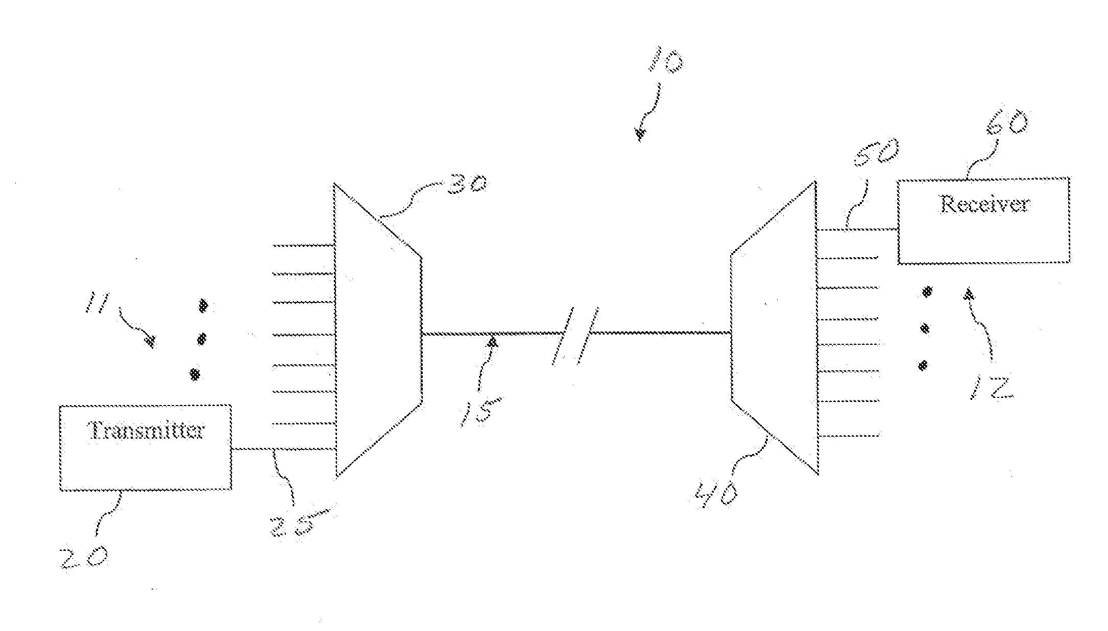
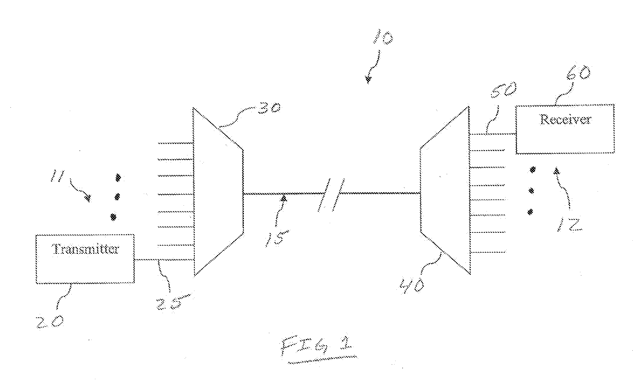
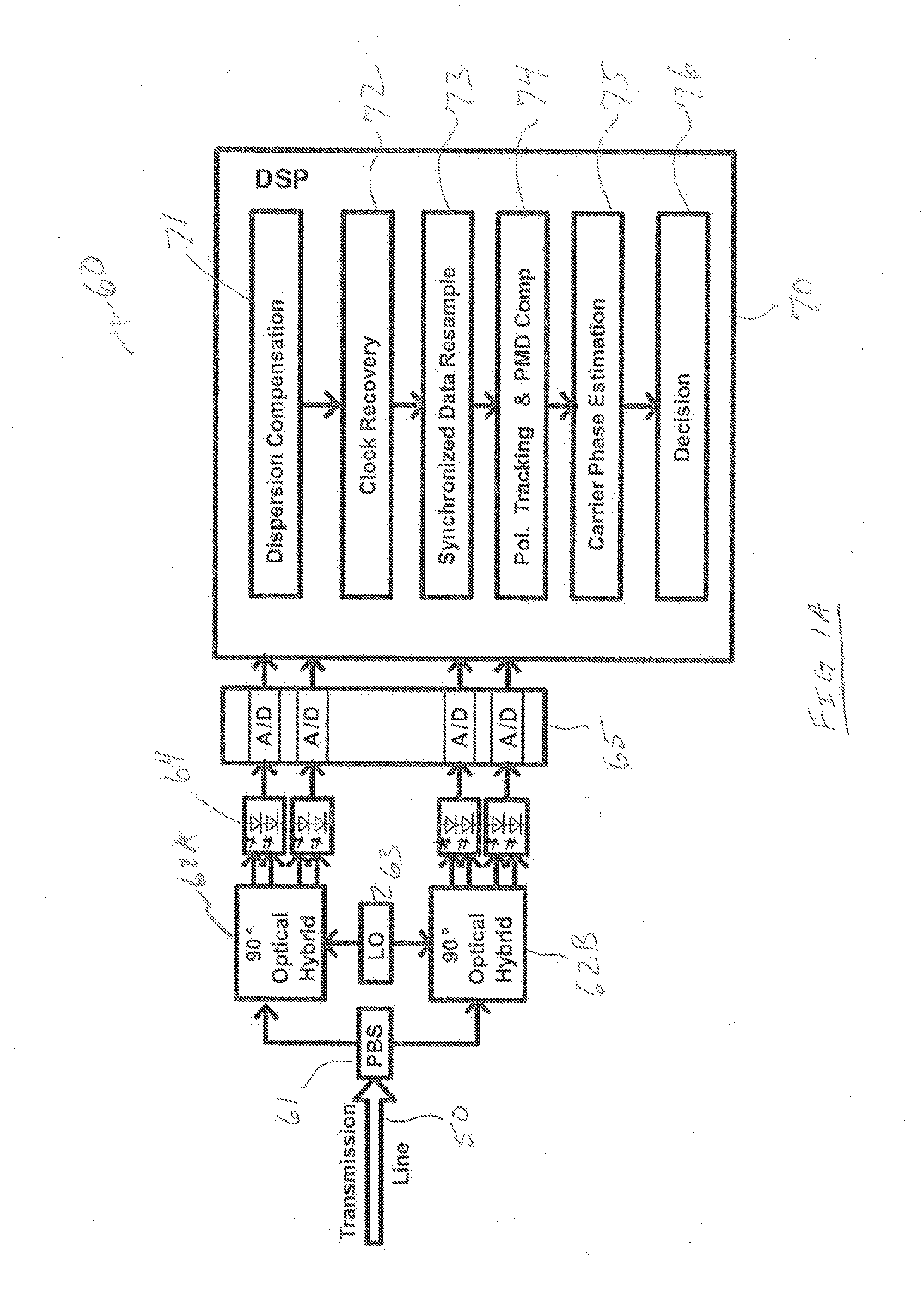
[0013]The present invention will now be described more fully hereinafter with reference to the accompanying drawings, in which preferred embodiments of the invention are shown. This invention, however, may be embodied in many different forms and should not be construed as limited to the embodiments set forth herein. Rather, these embodiments are provided so that this disclosure will be thorough and complete, and will fully convey the scope of the invention to those skilled in the art. In the drawings, like numbers refer to like elements throughout.

[0014]Presently disclosed embodiments mitigate the impact of nonlinear phase noise through improved carrier phase estimation with increased tracking capability. Phase ambiguity associated with carrier phase estimation may be removed by inserting one or more pilot symbols, which are reference symbols, inserted at known positions in a modulated optical signal. The one or more pilot symbols represent known data information and are inserted pe...


PUM


Abstract

Methods and systems for processing an optical signal in a communication system are disclosed. The disclosed methods yield benefits for estimation and tracking of carrier phase of received signals at a digital coherent receiver. Specifically, phase ambiguity is removed by the insertion of pilot symbols into a transmitted data stream. Pilot symbols are detected from a received signal, and carrier phase is estimated for the detected pilot symbols. If carrier phase track of received data symbols was lost, a correction is applied to recover the track. Coherent symbol decoding may be used which has not been possible with prior art techniques due to the possibility of phase tracking loss.

Description

FIELD OF THE INVENTION[0001]Embodiments of the present disclosure relate to the field of optical communication systems. More particularly, the present disclosure relates to the addition of pilot symbols in modulated optical signals to aid in joint polarization phase estimation in coherent optical receivers.DISCUSSION OF RELATED ART[0002]In optical communication systems, various modulation schemes are used to transmit optical signals using dense wavelength division multiplexing (DWDM) where a plurality of optical channels each at a particular wavelength propagate over fiber optic cables. However, various non-linearities including, for example, self-phase modulation (SPM) and cross-phase modulation (CPM) may induce nonlinear phase shifts which effect signal reception and decoding of these transmitted signals. After propagation over long distances, the impact of these non-linearities create processing and decoding difficulties at the receiver which may compromise the integrity of the t...

Claims


Application Information

Patent Timeline
Patent Type & Authority Applications(United States)
IPC IPC(8): H04B10/06
CPCH04B10/0779H04B10/61H04B10/6165H04B10/616H04B2210/074
Inventor ZHANG, HONGBINFOURSA, DMITRI
Owner SUBCOM LLC
Learn More