
Method of Preparing an Ankle Joint for Replacement, Joint Prosthesis, and Cutting Alignment Apparatus for Use in Performing an Arthroplasty Procedure

a technology of arthroplasty and ankle joint, applied in the field of preparation of ankle joint for replacement, can solve the problems of many devices failing, component crushing into the cancellous bone, failure of components,

Inactive Publication Date: 2011-11-10
DEPUY SYNTHES PROD INC
View PDF0 Cites 34 Cited by
  • Summary
  • Abstract
  • Description
  • Claims
  • Application Information

AI Technical Summary

Benefits of technology

This approach reduces bone resection, minimizes complications, and provides improved stability and motion, addressing the limitations of existing methods by allowing for a more effective and less invasive medial approach to ankle replacement.

Problems solved by technology

As is well known in the art, the more bone that is removed, or resealed, the more likely the failure of the component as the bone typically is its hardest at its outside surface.
Thus, many devices fail for reasons of subsidence of the component wherein the significant bone resection and the implanting of a component will cause the component to crush into the cancellous bone over time under pressure.
However, this preparation requires the devascularization of the fibula, release of the syndesmotic ligaments and significant bone resection.
Some of the most common problems encountered with prior art ankle prostheses are loosening of the components, instability, loss of bone support, subsidence, inadequate motion and noticeable scaring on the most visible parts of the ankle.
Further, and more importantly, ankle replacement is more challenging than other procedures such as hip or knee replacement due to the limited soft tissue envelope that is sparse at the ankle and has minimal flexibility.
Thus, ankle replacement is associated with a high complication rate.
Accordingly, wound problems are not uncommon due to the present techniques and prostheses known in the art.

Method used


Image

  • Method of Preparing an Ankle Joint for Replacement, Joint Prosthesis, and Cutting Alignment Apparatus for Use in Performing an Arthroplasty Procedure
  • Method of Preparing an Ankle Joint for Replacement, Joint Prosthesis, and Cutting Alignment Apparatus for Use in Performing an Arthroplasty Procedure
  • Method of Preparing an Ankle Joint for Replacement, Joint Prosthesis, and Cutting Alignment Apparatus for Use in Performing an Arthroplasty Procedure

Examples


Embodiment Construction

[0046]For purposes of the description hereinafter, the terms “upper”, “lower”, “right”, “left”, “vertical”, “horizontal”, “top”, “bottom”, “lateral”, “longitudinal” and derivatives thereof shall relate to the invention as it may be oriented in the drawing figures. However, it is to be understood that the invention may assume various alternative variations and step sequences, except where expressly specified to the contrary. It is also to be understood that the specific devices and processes illustrated in the attached drawings, and described in the following specification, are simply exemplary embodiments of the invention. Hence, specific dimensions and other physical characteristics related to the embodiments disclosed herein are not to be considered as unduly limiting. For example, certain portions of the invention are shown as oblong blocks having circular holes positioned therethrough, which could be configured in a number of shapes and manners as various embodiments of the inve...


PUM


Abstract

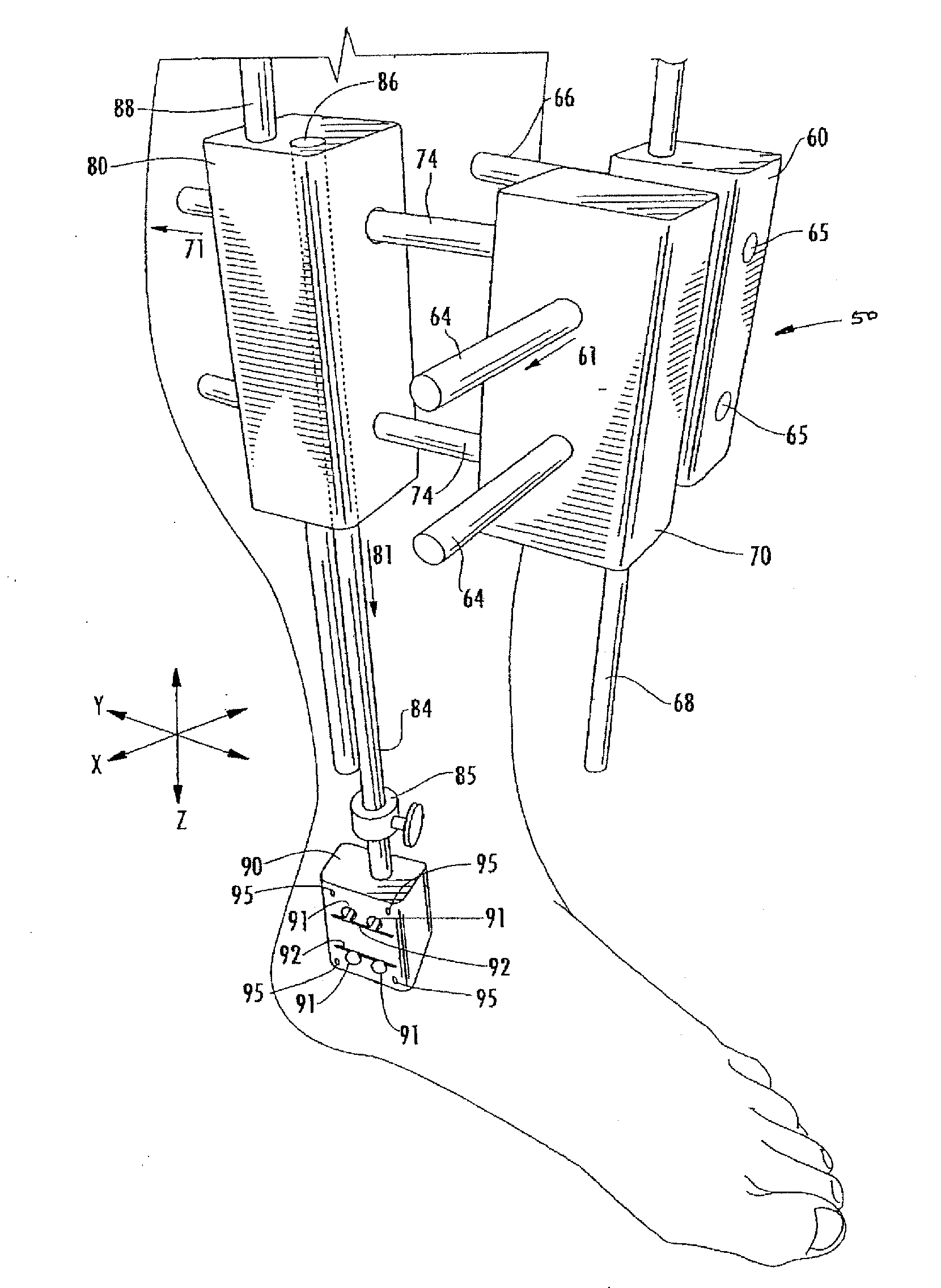
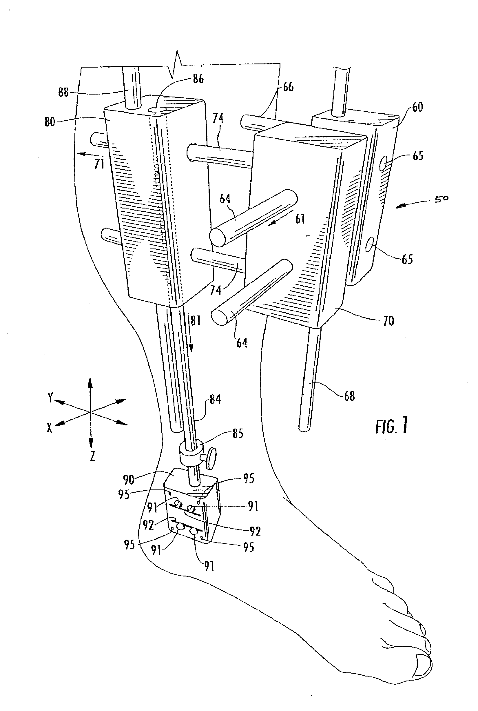
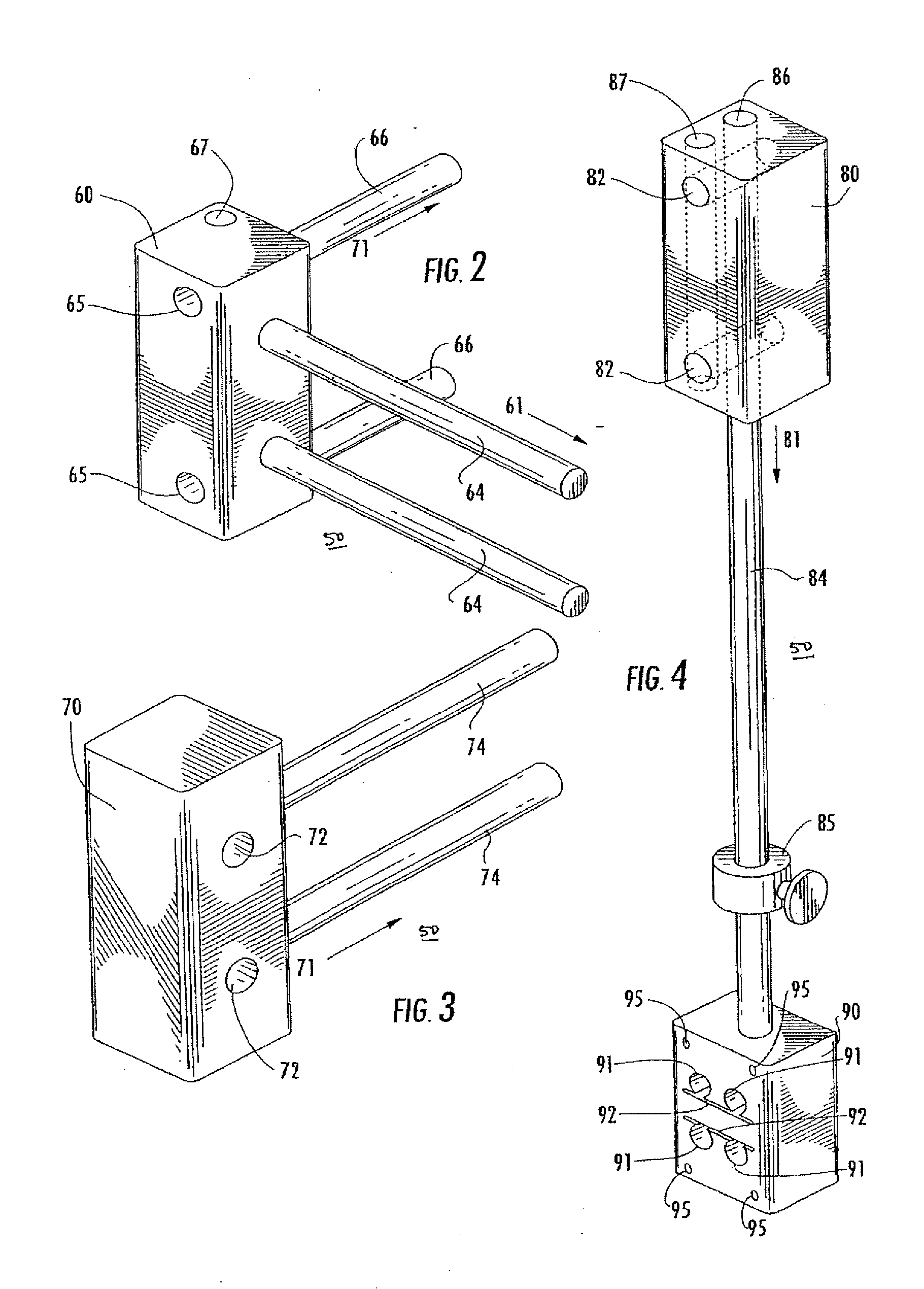
A method prepares an ankle joint of a patient for replacement. The patient includes a tibia (20) having a medial portion (22), a talus (40), and an ankle (10) having a medial portion. The method employs a cutting alignment apparatus (50) including a first portion external to the patient and a second portion, and surgically prepares and exposes the medial portion of the ankle for replacement. The second portion of the cutting alignment apparatus is coupled to the tibia, and a cutting guide (90) is disposed with respect to the cutting alignment apparatus. The medial portion of the tibia is detached, a portion of the tibia proximate the talus is cut, and a portion of the talus proximate the tibia is cut. An ankle prosthesis (100) is installed to the ankle, and the medial portion of the tibia is reattached.

Description

CROSS-REFERENCE TO RELATED APPLICATIONS[0001]This application claims the benefit of U.S. Provisional Pat. Appl. Ser. No. 60 / 761,007, filed Jan. 20, 2006; and of U.S. Provisional Pat. Appl. Ser. No. 60 / 781,634, filed Mar. 13, 2006.BACKGROUND OF THE INVENTION[0002]1. Field of the Invention[0003]This invention relates to a method of preparing an ankle joint for replacement, and more particularly to an ankle prosthesis and a method of preparing the ankle joint for replacement implementing such ankle prosthesis and an alignment apparatus that enables such replacement to be performed from a medial position on the ankle.[0004]2. Background Information[0005]Ankle prostheses and ankle replacement methods have been implemented for the past few decades producing numerous prostheses and approaches to the treatment of diseased, injured or otherwise compromised ankle joints. Many types of total ankle prostheses have been developed including a cylindrical-type ankle replacement, the spherical-type...

Claims


Application Information

Patent Timeline
Patent Type & Authority Applications(United States)
IPC IPC(8): A61B17/00
CPCA61B17/15A61F2/4202A61F2002/30232A61F2002/30357A61F2002/30649A61F2310/00029A61F2002/4205A61F2002/4207A61F2220/0033A61F2230/0069A61F2002/30891A61B17/1775
Inventor HASSELMAN, CARL T.
Owner DEPUY SYNTHES PROD INC
Learn More