Position detector, seat belt retractor having this position detector, and seat belt apparatus having this seat belt retractor

a position detector and detector technology, which is applied in the direction of safety belts, pedestrian/occupant safety arrangements, instruments, etc., can solve the problems of difficult to detect the rotation angle with a high degree of accuracy, and achieve the reduction of the variation between the detection points of the first and second magnetic detecting members, the effect of reducing the detection angle itself and reducing the difficulty of detection. the detection angl

Active Publication Date: 2011-11-17
JOYSON SAFETY SYST JAPAN GK
View PDF9 Cites 26 Cited by
  • Summary
  • Abstract
  • Description
  • Claims
  • Application Information

AI Technical Summary

Benefits of technology

[0020]The present invention is made in view of such circumstances, and an object thereof is to provide a position detector that can detect the position of a moving member with a higher degree of accuracy.
[0021]Another object of the present invention is to provide a seat belt retractor that can control the belt tension with a higher degree of accuracy according to the running state of the vehicle, the usage state of the seat belt apparatus, and the like, and a seat belt apparatus having this seat belt retractor.

Problems solved by technology

However, when such unipolar detection type magnetic detecting members are used to detect the N-pole magnets and S-pole magnets that are arranged alternately and have equal magnetization widths and to output the position of the moving member, there are the following problems.
However, if the ranges of detection and non-detection of rotation angle by the first and second Hall ICs 20a and 20b are different, a variation in detected angle is produced, and it is difficult to detect the rotation angle with a high degree of accuracy.

Method used


Image

  • Position detector, seat belt retractor having this position detector, and seat belt apparatus having this seat belt retractor
  • Position detector, seat belt retractor having this position detector, and seat belt apparatus having this seat belt retractor
  • Position detector, seat belt retractor having this position detector, and seat belt apparatus having this seat belt retractor

Examples


Embodiment Construction

[0051]The embodiments of the present invention will be described with reference to the drawings.

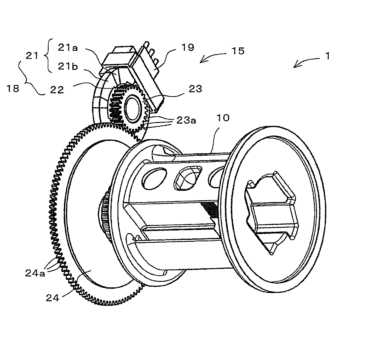
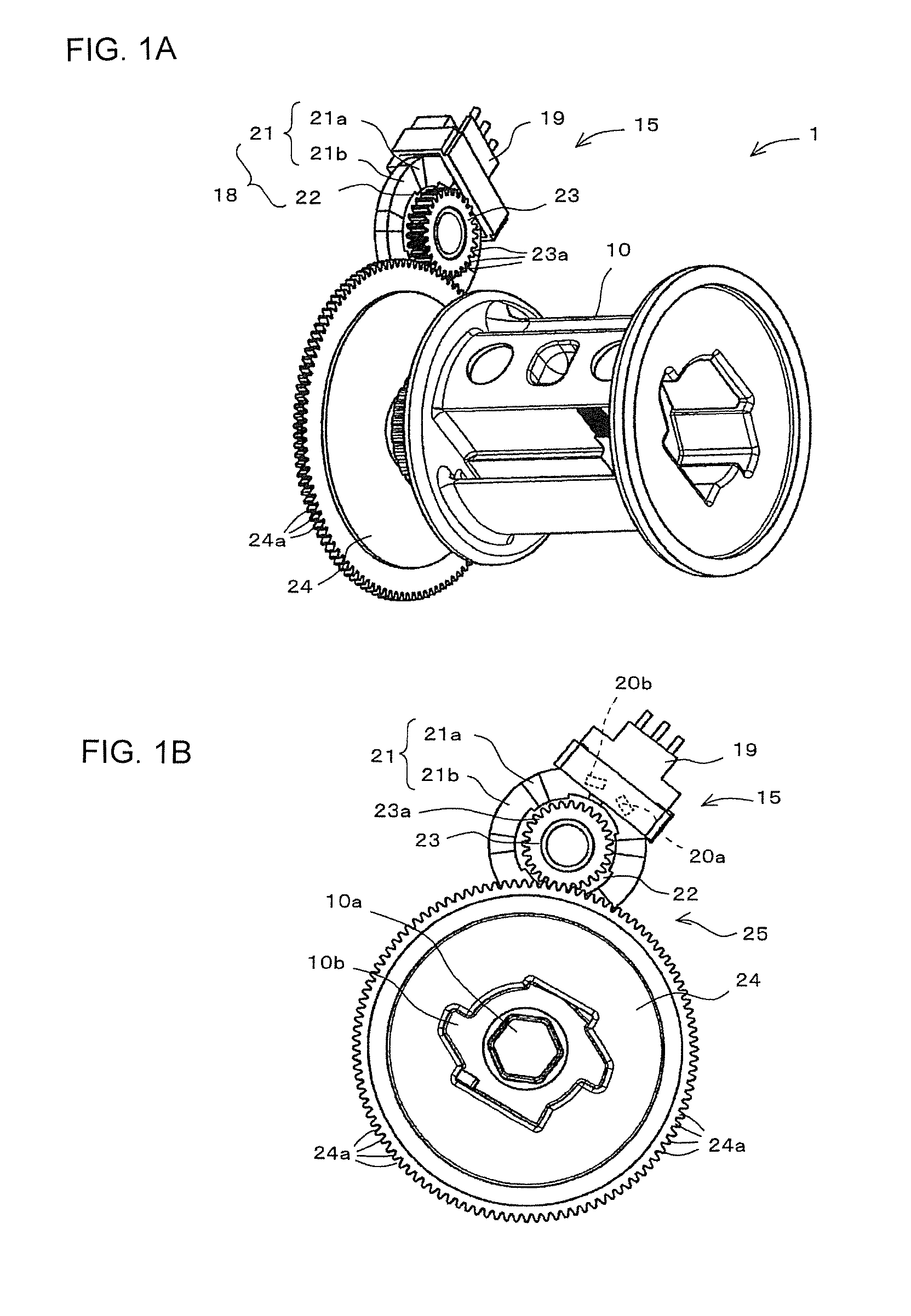
[0052]FIG. 1 partly shows a first example of an embodiment according to the present invention, FIG. 1A is a perspective view, and (b) is a right side view in FIG. 1A. In the description of the seat belt retractor and seat belt apparatus of this first example, the same reference numerals will be used to designate the same components as those of the seat belt retractor and seat belt apparatus described in Japanese Unexamined Patent Application Publication No. 2009-113718 shown in FIGS. 8 to 13, and the detailed description thereof will be omitted.

[0053]As shown in FIGS. 1A and 1B, the seat belt retractor 3 used in the seat belt apparatus of the first example has a rotation sensor 15 that is a position detector and a rotation amount detector disposed eccentrically relative to the rotating shaft 10a of the spool 10. This rotation sensor 15 has a rotating disk 18 rotatably attached to the righ...


PUM


Abstract

A position detector is provided that can detect the position of a moving member with a higher degree of accuracy. In one form, a rotation sensor includes a magnet in which N-pole magnets and S-pole magnets are arranged alternately and circularly and that rotates in conjunction with the rotation of a spool, and first and second Hall elements and that are disposed apart from each other in the circumferential direction of the magnet and detect the poles of the N-pole magnets and S-pole magnets. In that case, the first and second Hall elements and are both unipolar detection type Hall elements that detect only the S-pole. The magnetization width of the S-pole magnets is set large, and the magnetization width of the N-pole magnets is set small.

Description

CROSS-REFERENCE TO RELATED APPLICATIONS [0001]This application claims priority under 35 U.S.C. §119 to Japanese Patent Application No. JP2010-113155 filed on May 17, 2010, the entire content of which is hereby incorporated herein by reference in its entirety.FIELD OF THE INVENTION [0002]The present invention relates to the technical field of: a position detector including a unipolar detection type magnetic detecting member such as a Hall element that detects only the N-pole or S-pole, and a magnetic member in which N-poles and S-poles are arranged alternately and that moves in conjunction with the movement of a moving member (the term “moving member” includes a rotating member), wherein the position detector detects the position of the moving member by detecting only the N-poles or S-poles of the magnetic member using the magnetic detecting member; a seat belt retractor that detects the rotation amount of a spool using this position detector and thereby controls the rotation of the ...

Claims


Application Information

Patent Timeline
Patent Type & Authority Applications(United States)
IPC IPC(8): B60R22/34G01B7/14H01L43/06B65H75/48
CPCG01D5/145B60R22/34B60R22/46
Inventor IKEDA, KENJI
Owner JOYSON SAFETY SYST JAPAN GK
Why Eureka
Try Eureka