Printing apparatus

Active Publication Date: 2011-11-17
CANON KK
View PDF5 Cites 11 Cited by
  • Summary
  • Abstract
  • Description
  • Claims
  • Application Information

AI Technical Summary

Benefits of technology

[0007]The invention is achieved on the basis of recognition of the above-described problems. The present invention provides a method of preventing printing on splices when printing a plurality of images in sequence on a continuous sheet having at least one splice and ensuring avoidance of contact of the splice of the continuous sheet with a print head.
[0009]According to the embodiment, printing on splices is prevented when printing a plurality of images in sequence on a continuous sheet having a splice and contact of the splice of the continuous sheet with a print head is avoided.

Problems solved by technology

When the printing is started before the splice leaves completely from under the print head, since the gap between a nozzle surface and the sheet is larger than the normal condition, the positional displacement of ink dots and, by extension, image failure may occur, or the amount of generated ink mist may increase.

Method used


Image

  • Printing apparatus
  • Printing apparatus
  • Printing apparatus

Examples


Embodiment Construction

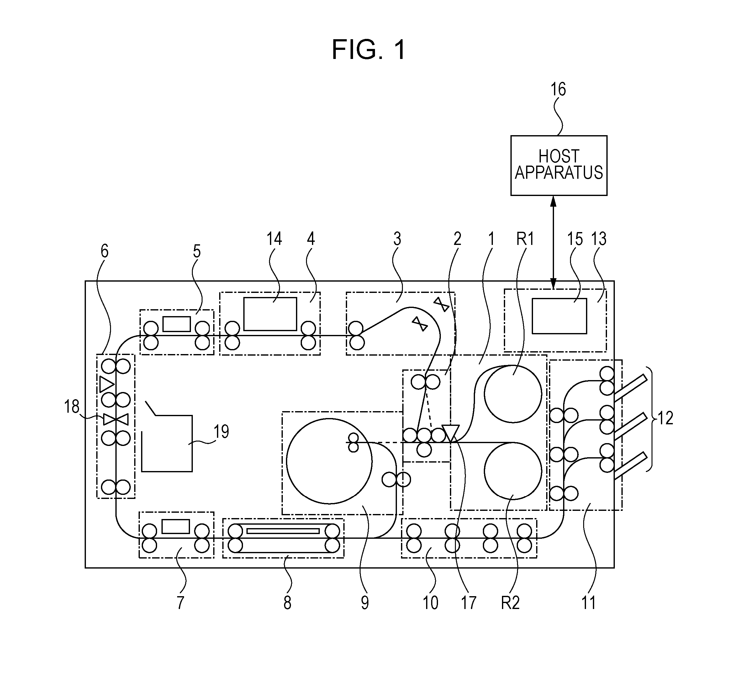
[0021]An embodiment of an inkjet printing apparatus will now be described. The printing apparatus in this embodiment is a high-speed line printer using an elongated continuous sheet (an elongated continuous sheet longer than a print unit (referred to as one page or unit image) repeated in the direction of conveyance) and supporting both simplex printing and duplex printing. For example, this high-speed line printer is suitable for a field such as a print laboratory where a large amount of printing is performed. In this specification, even when a plurality of small images, characters, and spaces are mixed in an area of a single print unit (one page), all those included in the area are collectively referred to as a unit image. In other words, the unit image means one print unit (one page) when printing a plurality of pages in sequence on the continuous sheet. It may be referred to simply as an image instead of the unit image. The length of the unit image depends on the image size to b...


PUM


Abstract

An apparatus includes an adjusting mechanism configured to change a gap between a print head and a continuous sheet, and the adjusting mechanism controls the gap to be larger than that at the time of printing when a splice of the continuous sheet passes the print head. An unprintable area is set on each of the upstream side and the downstream side of the splice, each having at least a width corresponding to a sum of a length of the plurality of print heads in the direction of sheet conveyance and a distance of movement of the continuous sheet in a period required for the adjusting mechanism to change the gap, and the printing is continued while avoiding the unprintable area.

Description

BACKGROUND OF THE INVENTION[0001]1. Field of the Invention[0002]The present invention relates to a printing apparatus configured to perform printing using a continuous sheet.[0003]2. Description of the Related Art[0004]Rolled continuous sheets are used for a large amount of printing as in the case of a laboratory printing. When manufacturing rolled continuous sheets, in terms of improvement of production yield, there is a case of connecting ends of a plurality of continuous sheets having insufficient lengths with a fixing material such as a splicing tape (hereinafter referred to as “tape”) so that a roll having a required length is achieved. This rolled continuous sheet has splices (joined portion) joined with the tape at one or more random positions.[0005]An apparatus disclosed in Japanese Patent Laid-Open No. 2001-239715 is configured to sense the position of the splices by detecting the tape using an optical sensor, set unrecordable areas including the splices, and control not to...

Claims


Application Information

Patent Timeline
IPC IPC(8): B41J29/38
CPCB41J3/60B41J25/308B41J11/70B41J11/008
Inventor TAKEUCHI, TOSHIKIKAWAGUCHI, KOICHIRONIEDA, KENGO
Owner CANON KK
Why Eureka
Try Eureka