
Optical scanning device and image forming apparatus

a scanning device and scanning technology, applied in the direction of electrographic process equipment, printing, instruments, etc., can solve the problems of low effect of difficult technique, f lens, etc., to achieve the effect of effectively adjusting the amount of deformation of the optical element, and reducing the curvature of the scanning lin

Inactive Publication Date: 2011-11-17
SHARP KK
View PDF7 Cites 0 Cited by
  • Summary
  • Abstract
  • Description
  • Claims
  • Application Information

AI Technical Summary

Benefits of technology

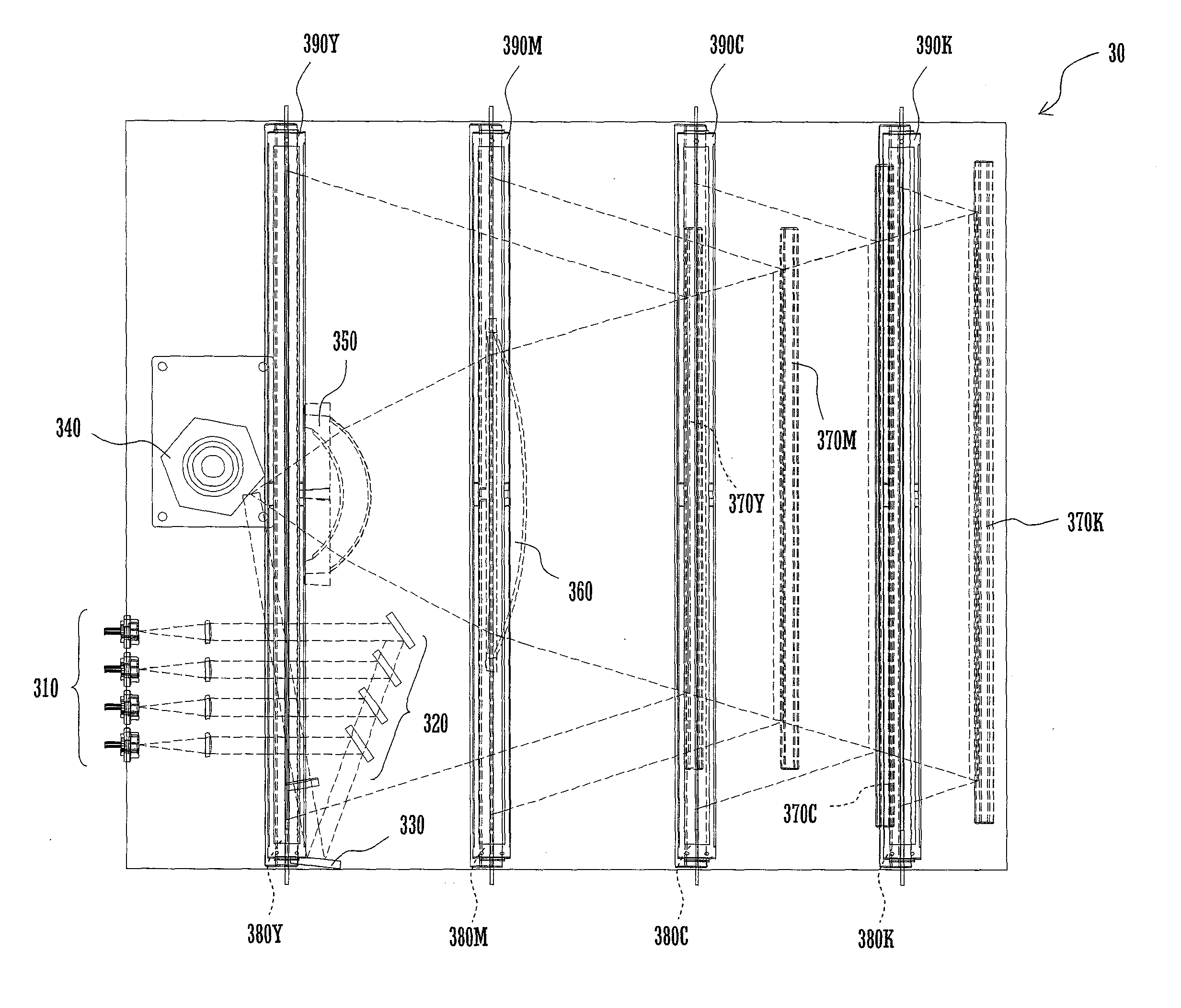
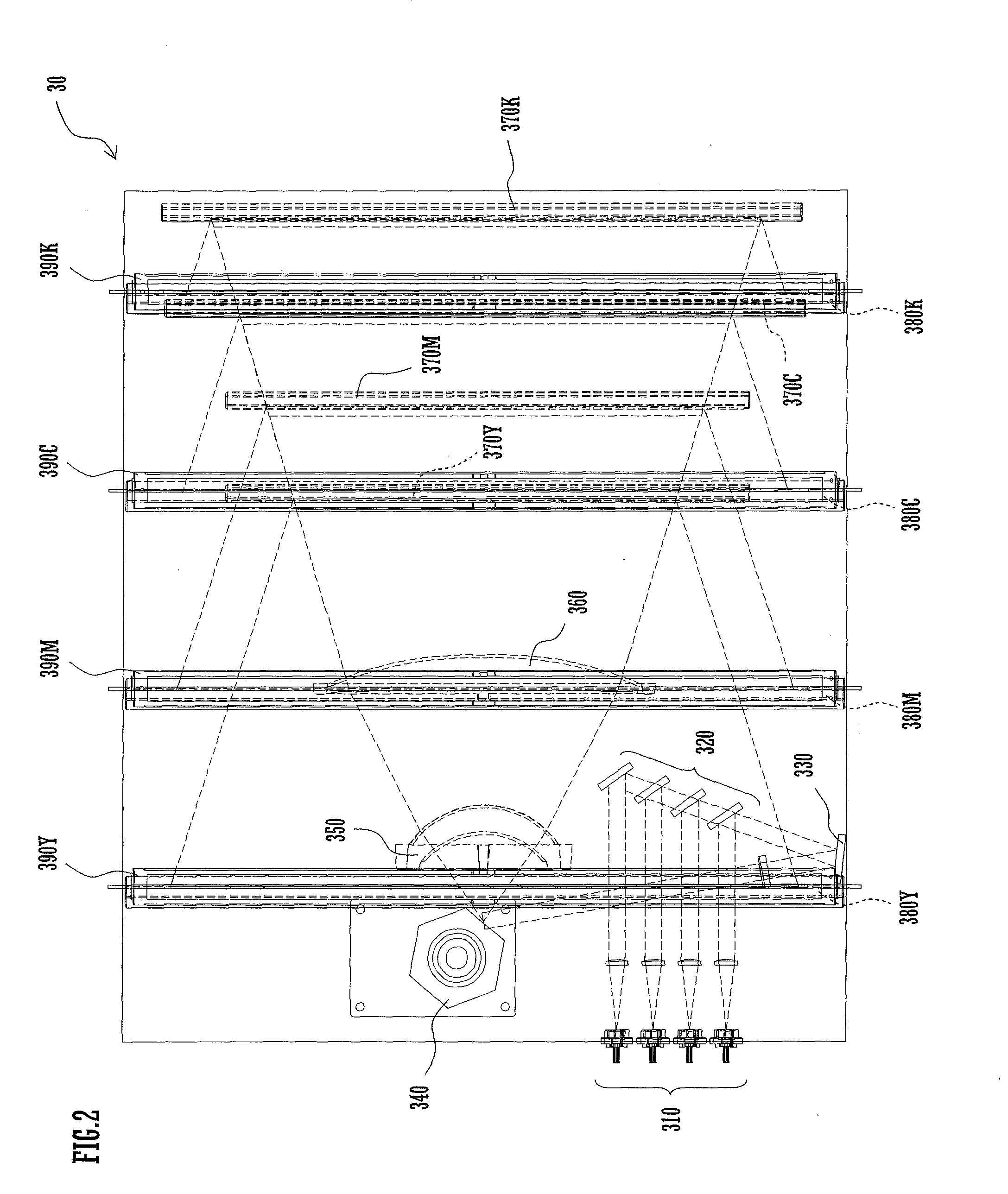
[0013]Since this arrangement is capable of deforming the optical element by using the single first pressing section to press w against the first adjusting section which is capable of pressing against the optical element at the plural points, the amount of deformation of the optical element can be adjusted easily. Specifically, by moving the first pressing section parallel with the longitudinal direction of the optical element, the point of effort of the first pressing section on the first adjusting section can be shifted, which makes it possible to adjust the pressing force of each projection against the optical element easily.
[0014]Since this arrangement is capable of pressing against the optical element at the plural points, the optical element can be deflected at plural portions thereof. Therefore, the arrangement according to the present invention is capable of easily adjusting the amount of deformation of the optical element while effectively reducing the curvature of a scanning line.

Problems solved by technology

However, the fθ lens has a problem that a scanning line passing therethrough curves because the internal structure of the fθ lens has changed during a cooling process carried out after the molding of the fθ lens.
With the provision of the adjusting screw only at the longitudinally central portion of the fθ lens, however, the effect of reducing the curvature of a scanning line is low because even though the fθ lens is deformed by the adjusting screw pressing against the fθ lens, only the central portion of the fθ lens is deflected.
It is, however, difficult for the technique described in the Patent Application noted above to deform the fθ lens to such an extent as to minimize the curvature of a scanning line because the screws provided at the three points need to be adjusted individually.

Method used


Image

  • Optical scanning device and image forming apparatus
  • Optical scanning device and image forming apparatus
  • Optical scanning device and image forming apparatus

Examples


first embodiment

[0032]Description will be made of a

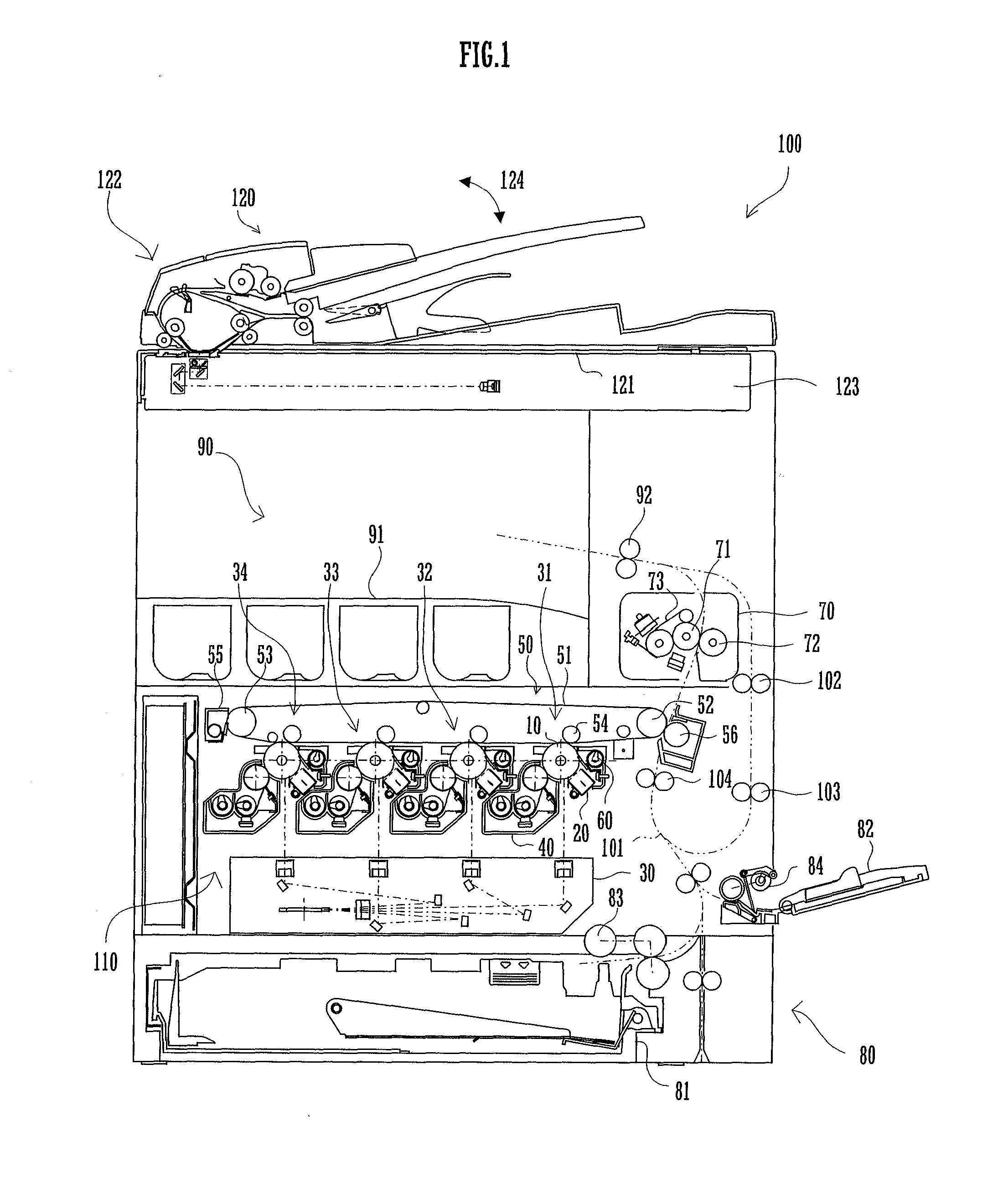
[0033]FIG. 1 is a view illustrating the structure of an image forming apparatus 100 incorporating an optical scanning device 30 according to the first embodiment of the present invention.

[0034]The image forming apparatus 100 is configured to form a polychrome or monochrome image on a predetermined sheet (i.e., recording sheet) in accordance with image data transmitted thereto from the outside. The image forming apparatus 100 includes a document processing device 120, a sheet feeding section 80, an image forming section 110, and an output section 90.

[0035]The document processing device 120 includes a document platen 121, a document feeder 122, and a document reading section 123. The document platen 121 is formed of transparent glass and is designed to allow a document to be placed thereon. The document feeder 122 feeds documents loaded on a document load tray one by one. The document feeder 122, which is capable of pivoting in a direction indicated ...

second embodiment

[0073]Description will be made of the present invention.

[0074]FIG. 6 illustrates a relevant portion of the structure of the optical scanning device 30 according to the second embodiment of the present invention. Throughout the second to fourth embodiments, redundant description will not be made of the features having been already described in relation to the first embodiment.

[0075]FIG. 6A is a plan view illustrating the relevant portion of the structure of the optical scanning device 30, and FIG. 6B is a right side view illustrating the relevant portion of the structure of the optical scanning device 30. In the present embodiment, the pressing portion 395 has a cam portion 400 instead of the columnar member 396. The pressing portion 395 is formed with a threaded hole for mounting the cam portion 400.

[0076]The cam portion 400 is formed with a screw portion on the side to be fitted on the pressing portion 395 and, hence, the screw portion is threadingly engageable with the threaded ho...

third embodiment

[0078]Description will be made of the present invention.

[0079]FIG. 7 illustrates a relevant portion of the structure of the optical scanning device 30 according to the third embodiment of the present invention.

[0080]Specifically, FIG. 7A is a plan view illustrating the relevant portion of the structure of the optical scanning device 30, and FIG. 7B is a right side view illustrating the relevant portion of the structure of the optical scanning device 30. In the present embodiment, the optical scanning device 30 is provided with a holder 401 which is removable from the optical scanning device 30 and which holds the third fθ lens 390, adjusting bar 391, pressing portion 395, columnar member 396 and movement restraining section 397 as a unity.

[0081]In the arrangement according to the present embodiment, the members for deforming the third fθ lens 390 are held by the single holder 401 and, hence, the holder 401 and the members for deforming the third fθ lens 390 can be handled as one uni...


PUM


Abstract

An optical scanning device includes a third fθ lens, an adjusting bar, a pressing portion, a columnar member, and a movement restraining section. The adjusting bar is disposed parallel with a longitudinal direction of the third fθ lens and has projections which are capable of pressing against the third fθ lens at plural points in the longitudinal direction of the third fθ lens. The pressing portion and the columnar member press the adjusting bar against the third fθ lens. The movement restraining section is configured to set the pressing portion and the columnar member in a first state in which the pressing portion and the columnar member are movable in a direction parallel with the longitudinal direction of the third fθ lens or in a second state in which the pressing portion and the columnar member are restrained from moving.

Description

CROSS REFERENCE[0001]This Nonprovisional application claims priority under 35 U.S.C. §119(a) on Patent Application No. 2010-112105 filed in Japan on May 14, 2010 the entire contents of which are hereby incorporated by reference.BACKGROUND OF THE INVENTION[0002]The present invention relates to an optical scanning device capable of reducing curvature of a scanning line, as well as an image forming apparatus incorporating such an optical scanning device.[0003]In an electrophotographic image forming apparatus, an optical scanning device is used to apply a scanning line onto a photoreceptor in order to form an electrostatic latent image thereon. Such an optical scanning device includes a plurality of optical elements (i.e., fθ lenses). A scanning line passes through these fθ lenses to reach the photoreceptor.[0004]Therefore, such an fθ lens is required to have the function of transmitting a scanning line therethrough with high precision in order for the scanning line to be applied to a p...

Claims


Application Information

Patent Timeline
Patent Type & Authority Applications(United States)
IPC IPC(8): B41J2/385G02B26/08
CPCB41J2/473G02B26/123G03G2215/0132G03G15/011G03G15/0435G02B26/125
Inventor ONO, YASUHIRO
Owner SHARP KK
Learn More