
Laser lighting apparatus and method

a technology of laser lighting and laser beams, applied in lighting applications, instruments, television systems, etc., can solve the problems of narrow hallways and small rooms, and achieve the effect of facilitating the lighting of the correct area

Active Publication Date: 2011-11-17
REDPATH JAMES +2
View PDF5 Cites 9 Cited by
  • Summary
  • Abstract
  • Description
  • Claims
  • Application Information

AI Technical Summary

Benefits of technology

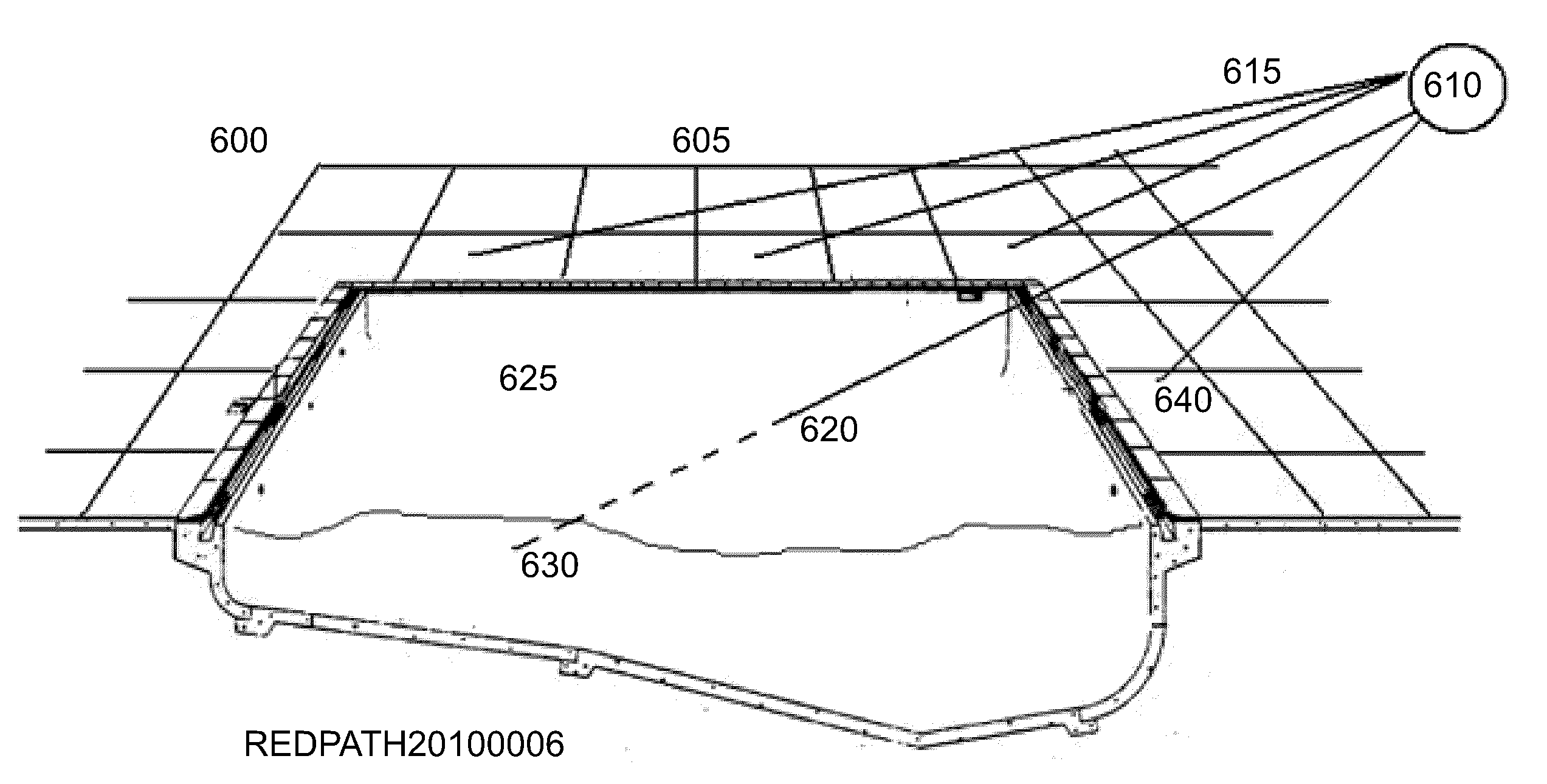
[0007]It is a further object of the invention for a directional fire evacuation system that can dot light a individual to lead them toward the exit there by providing depth perception and forward visibility. Additionally, the system is to provide a less complicated infrastructure for installation and less failure points to operate as well as some aspects to be more successful for exit paths to be acknowledge that maybe blocked by flames and limited smoke.

Problems solved by technology

Proper area lighting is difficult for narrow hallways and small rooms.
Unfortunately the laser light is not used to project dots of light refracting (bending) on the surfaces to identify planes radiating along the way to guide an individual toward the exit in providing depth perception and forward visibility.

Method used


Image

  • Laser lighting apparatus and method
  • Laser lighting apparatus and method
  • Laser lighting apparatus and method

Examples


Embodiment Construction

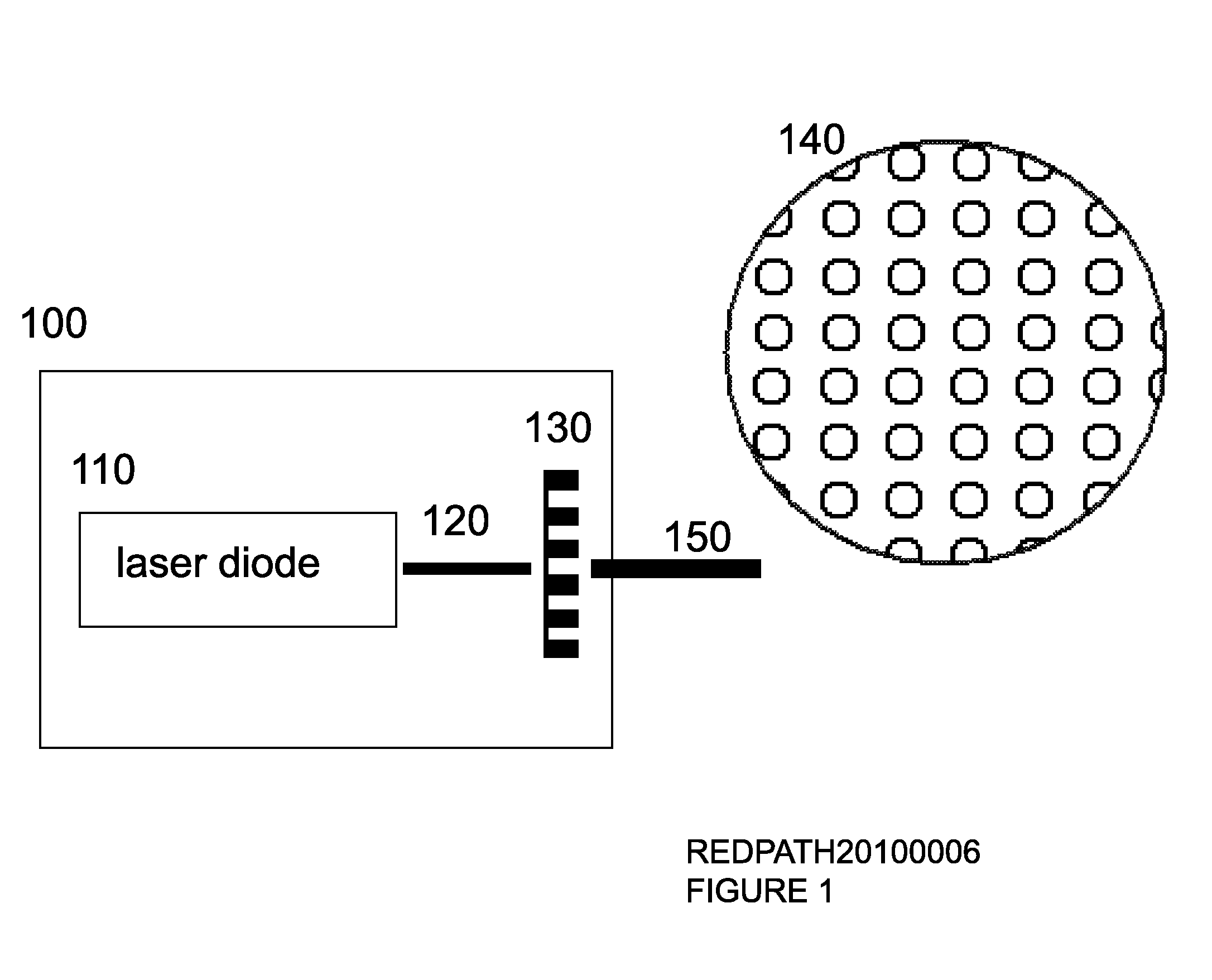
[0013]Referring to FIG. 1 at 100 is the embodiment which is constructed of a laser diode at 110 producing a beam at 120 to be incident with diffraction grating at 130. At 140 is a cross section of the output beam at 150 from the diffraction grating at 130. One skilled in the art of creating enclosures for lighting can be referenced to apply an enclosure for the embodiment as a product.

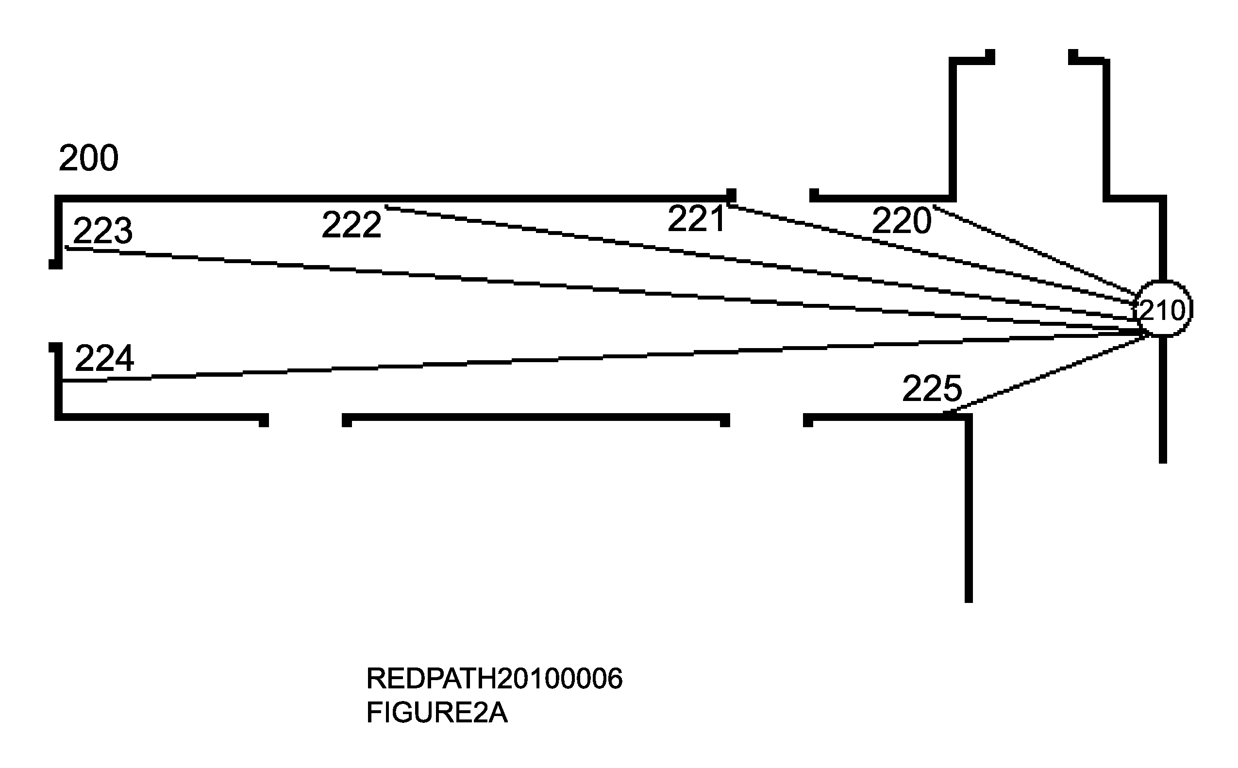
[0014]Referring to FIG. 2a at 200 is an architectural drawing for a hallway. At 210 the embodiment in FIG. 1 at 100 is placed as to illuminate the hallway at 200. More specifically referring to FIG. 1 at 150 the diffraction output is positioned as to illuminate the hallway in FIG. 2a at 200. At 220 thru 225 the diffraction grating output in FIG. 1 at 150 will incident three dimensionally the hallway referring to FIG. 2a at 200 producing dots and lines for a very complete illumination of a narrow area.

[0015]Referring to FIG. 2b at 300 is an architectural drawing for a small room. The embodiment in FIG. ...


PUM


Abstract

Disclosed is a laser light system for narrow hallways, a night light for small rooms, and a fire evacuation system. The system provides a means for less infrastructure to light narrow and small areas as well as directional lighting for fire escape.

Description

BACKGROUND OF INVENTION[0001]Proper area lighting is difficult for narrow hallways and small rooms. It is common for an infrastructure of wiring and or fiber optics to be utilized to achieve lighting along stepped areas or simply to have a wide reflective base light such as a plug in night light for radial illumination or side wall mounted units.[0002]Prior art which demonstrates the need for complex infrastructures is a laser light fire evacuation system in which columns of laser light are wired into the ceiling using fiber optics and embedded laser diodes controlled by a central unit with possible mechanical apparatus such as a rotating mirror adding many points of failure. Laser light is used in this fire escape system to overcome the less visibility of the sequencing of lights when the smoke becomes thick. Additionally the columns of light are serially staged to turn on as to lead for escape. Unfortunately the laser light is not used to project dots of light refracting (bending)...

Claims


Application Information

Patent Timeline
IPC IPC(8): F21V33/00F21S8/00
CPCF21V33/0076G08B7/066F21Y2101/025F21W2131/401F21Y2101/00F21Y2115/30
Inventor REDPATH, RICHARDREDPATH, JAMES
Owner REDPATH JAMES
Learn More