Pump, pump arrangement and pump module

a technology of pump module and pump arrangement, which is applied in the direction of liquid fuel engine components, positive displacement pump components, etc., can solve the problem of relatively small achievable pressure of micro diaphragm pumps

Active Publication Date: 2011-11-17
FRAUNHOFER GESELLSCHAFT ZUR FOERDERUNG DER ANGEWANDTEN FORSCHUNG EV
View PDF8 Cites 29 Cited by
  • Summary
  • Abstract
  • Description
  • Claims
  • Application Information

AI Technical Summary

Benefits of technology

According to an embodiment, a pump may have: an inlet opening; an outlet opening; a pump diaphragm including an opening, provided with a passive check valve, through the pump diaphragm; an actuator configured to move the pump diaphragm between a first position and a second position, wherein the passive check valve is configured such that a movement from the first position in the direction toward the second position has a closing effect, and that a movement from the second position in the direction toward the first position has an opening effect, so that a pumping cycle wherein the pump diaphragm is moved from the first to the second positions, and back, causes a net flow from the inlet opening to the outlet opening; a further pump diaphragm including an opening, provided with a further check valve, through the further pump diaphragm; a further actuator configured to move the further pump diaphragm between a third position and a fourth position; and a spacer arranged between the pump diaphragm and the further pump diaphragm which, along with the pump diaphragms, defines a pump chamber, wherein the outlet opening is formed by the opening within the pump diaphragm and is provided with the passive check valve, and wherein the inlet opening is formed by the opening within the further pump diaphragm and is provided with the further passive check valve, wherein the actuator and the further actuator are configured to move the pump diaphragm and the further pump diaphragm such that the volume of the pump chamber is increased during a suction phase, and that the volume of the pump chamber is reduced during a pumping phase, wherein the check valve is configured such that a movement of the pump diaphragms during the suction phase has a closing effect, and that a movement of the pump diaphragms during the pumping phase has an opening effect, and wherein the further check valve is configured such that a movement of the pump diaphragms during the suction phase has an opening effect, and that a movement of the pump diaphragms during the pumping phase has a closing effect.
Embodiments of the present invention comprise two pump diaphragms having through-openings—provided with check valves—and respective actuation means for same. The pump diaphragms may have a spacer provided between them which along with the pump diaphragms defines a pump chamber. The outlet opening may be formed by means of the opening in one of the pump diaphragms, whereas the inlet opening may be formed by means of the openings of the other pump diaphragms. The actuation means may be configured to move the pump diaphragms such that the volume of the pump chamber is increased during a suction phase, and such that the volume of the pump chamber is reduced during a pumping phase. In the suction phase, the movement of the pump diaphragms may have the effect of closing one of the check valves and of opening the other, whereas during the pumping phase the movement of the pump diaphragms may have the effect of opening one of the check valves and of closing the other one of the check valves.

Problems solved by technology

However, known micro diaphragm pumps only achieve delivery rates of 0.02 l / min for water and 0.05 l / min with air, and the achievable pressures of micro diaphragm pumps are relatively small while having a maximum counterpressure (with compressible gas as the volume to be delivered) of about 400 hPa.

Method used


Image

  • Pump, pump arrangement and pump module
  • Pump, pump arrangement and pump module
  • Pump, pump arrangement and pump module

Examples


Embodiment Construction

Before addressing the individual figures, it shall be noted that in said figures elements that are identical or have identical actions are designated by the same reference numerals in each case, multiple descriptions of said elements being dispensed with.

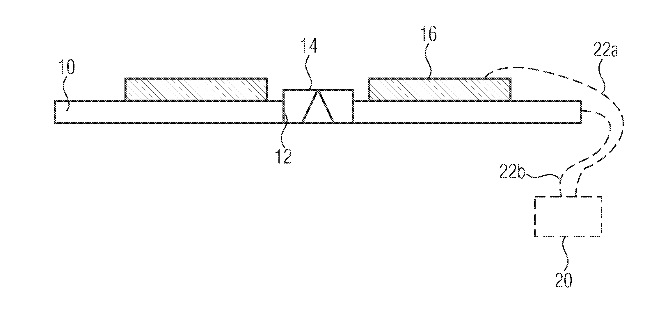
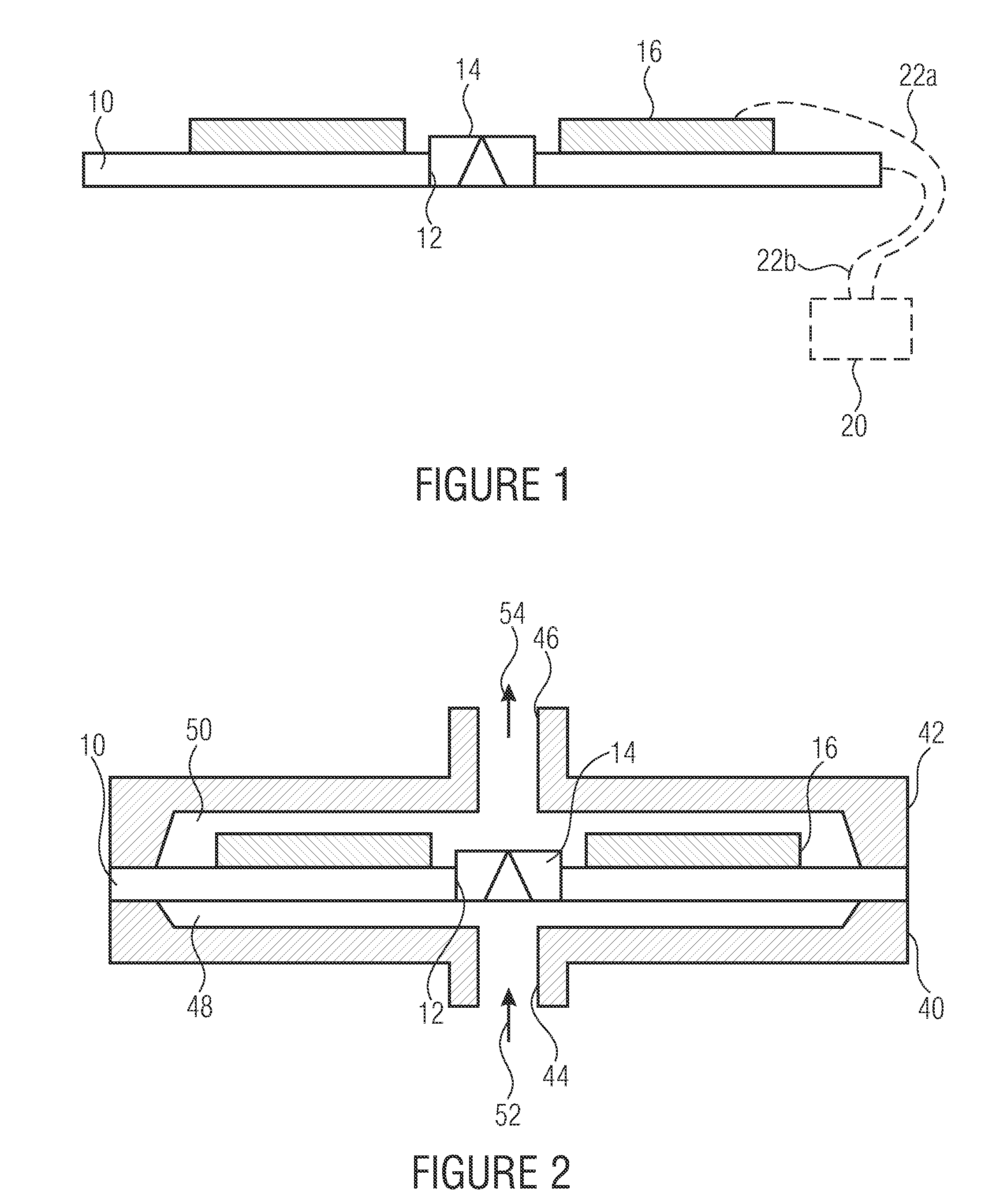
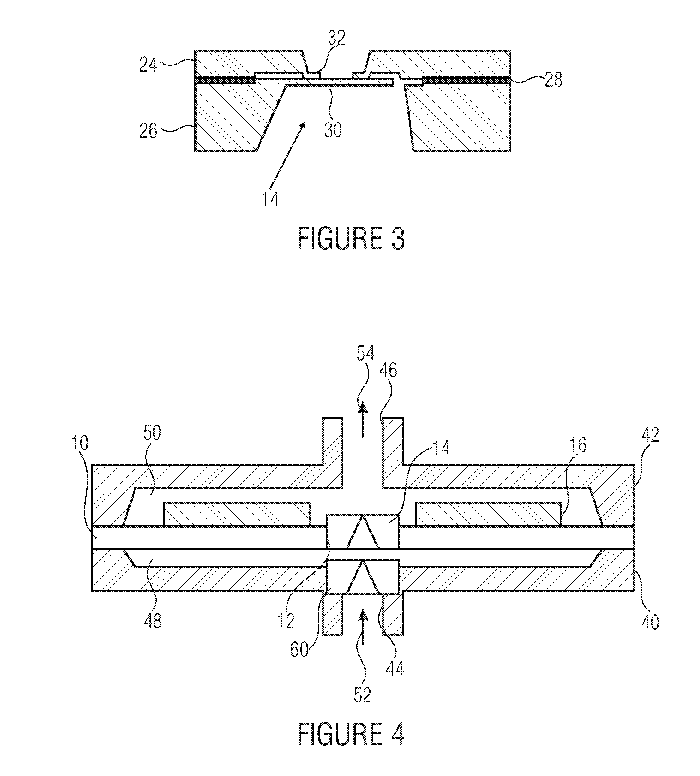
An embodiment of an inventive pump module is shown in FIG. 1. The pump module comprises a pump diaphragm 10, a through-opening 12 provided with a passive check valve 14, and a piezoceramic 16 arranged on the pump diaphragm 10. As viewed from the top, the pump diaphragm 10 may have a circular circumference, for example, it being possible for the through-opening 12 comprising the passive check valve 14 to be centrally arranged. The piezoceramic 16 may then annularly surround the through-opening 12.

Schematically, FIG. 1 depicts, in dashed lines, a control means 20 that may be configured to apply a voltage difference to the piezoceramic 16 via corresponding electric connections 22a and 22b so as to effect actuation of the pump diaphragm...


PUM


Abstract

A pump has an inlet opening, an outlet opening, a pump diaphragm comprising an opening, provided with a passive check valve, through the pump diaphragm, and an actuator configured to move the pump diaphragm between a first position and a second position. The passive check valve is configured such that a movement from the first position in the direction toward the second position has a closing effect, and that a movement from the second position in the direction toward the first position has an opening effect, so that a pumping cycle wherein the pump diaphragm is moved from the first to the second positions, and back, causes a net flow from the inlet opening to the outlet opening.

Description

Embodiments of the present invention relate to a pump, a pump arrangement and a pump module, and in particular to a pump, a pump arrangement and a pump module that operate using a pump diaphragm and are suitable for micro design.BACKGROUNDKnown compressors for pressure ranges above 10 bar are typically 1- or 2-stage piston cylinder systems comprising a power-efficient electric motor and a design volume that is too large for micro systems.Minimal compressors having a design volume of less than 1 dm3 are mostly diaphragm pumps with an electric drive. For such minimal compressors, maximum pressure ranges of up to 2 bar are indicated.By contrast, there are piezoelectric micro diaphragm pumps comprising passive check valves having an installation space of only a few cm3. An exemplary micro diaphragm pump is known from DE 19719862 A1. Said micro diaphragm pump comprises a pump diaphragm that may be moved to first and second positions by a driving means. A pump body is connected to the pum...

Claims


Application Information

Patent Timeline
Patent Type & Authority Applications(United States)
IPC IPC(8): F04B53/10
CPCF04B43/04F04B53/1047F04B43/046F04B23/06
Inventor WACKERLE, MARTINKRUCKOW, JUERGENRICHTER, MARTINHEINRICH, KLAUS
Owner FRAUNHOFER GESELLSCHAFT ZUR FOERDERUNG DER ANGEWANDTEN FORSCHUNG EV
Why Eureka
Try Eureka