Cushion clip

Active Publication Date: 2011-11-24
DAIWA KASEI IND CO LTD
View PDF17 Cites 13 Cited by
  • Summary
  • Abstract
  • Description
  • Claims
  • Application Information

AI Technical Summary

Benefits of technology

[0007]According to the aspect of the invention, when the compression force is applied to the cushioning portion, the compression force can be effectively dispersed. That is, a stress cannot be concentrated to the cushioning portion along the outer circumferential periphery of the end surface of the connecting portion. As a result, the whole cushioning portion can be uniformly compressed and elastically deformed. Thus, even when the cushioning

Problems solved by technology

As a result, a folding line cannot substantially be formed i

Method used


Image

  • Cushion clip
  • Cushion clip
  • Cushion clip

Examples


Embodiment Construction

[0019]Next, representative embodiments of the present invention will be described with reference to the drawings.

First Detailed Representative Embodiment

[0020]A first detailed representative embodiment of the present invention will be described with reference to FIGS. 1 to 4.

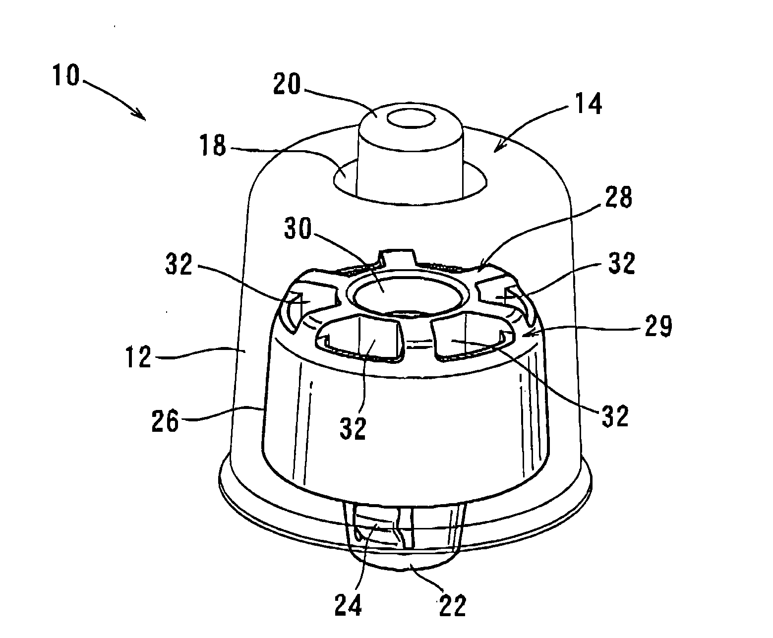
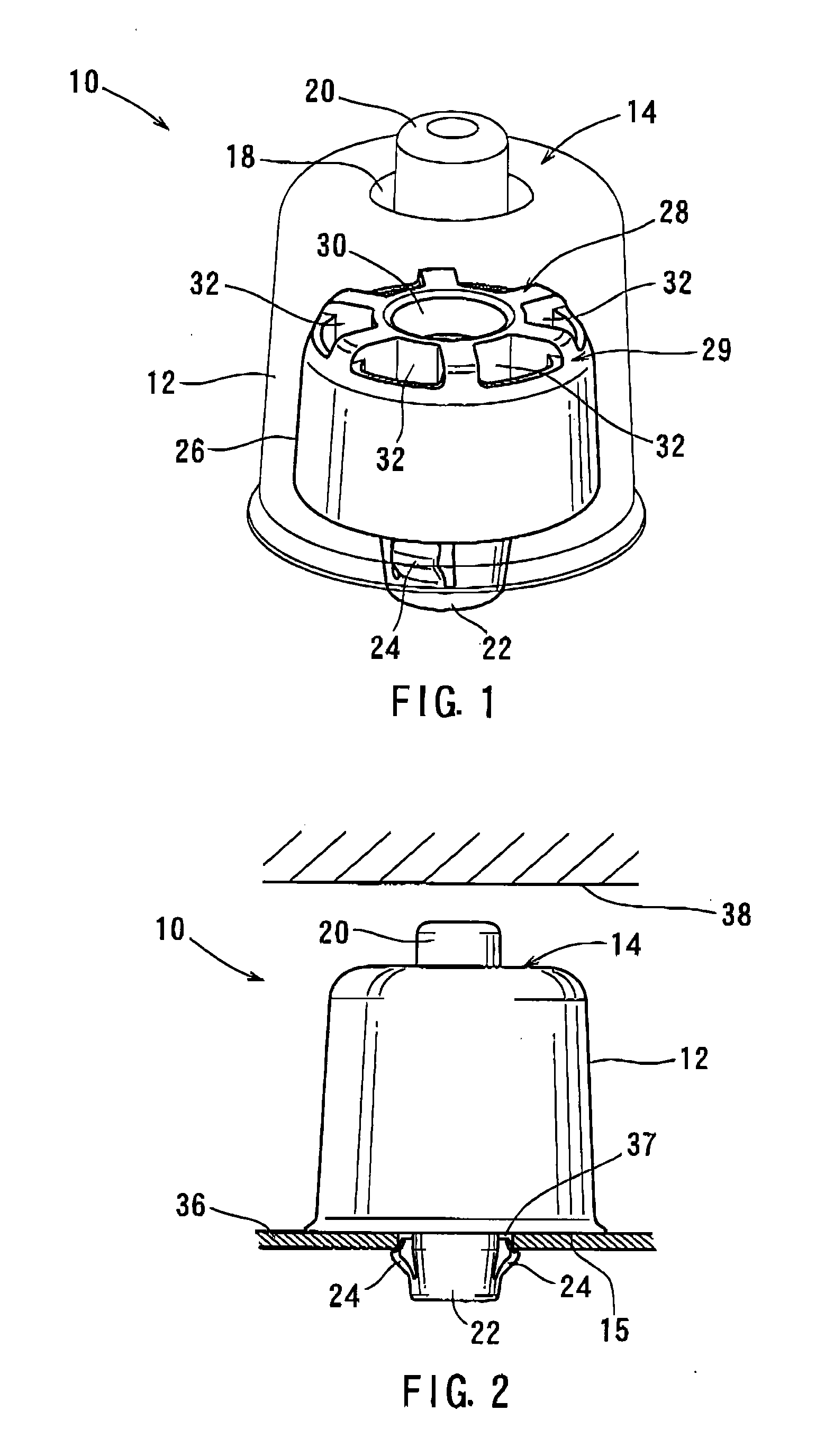
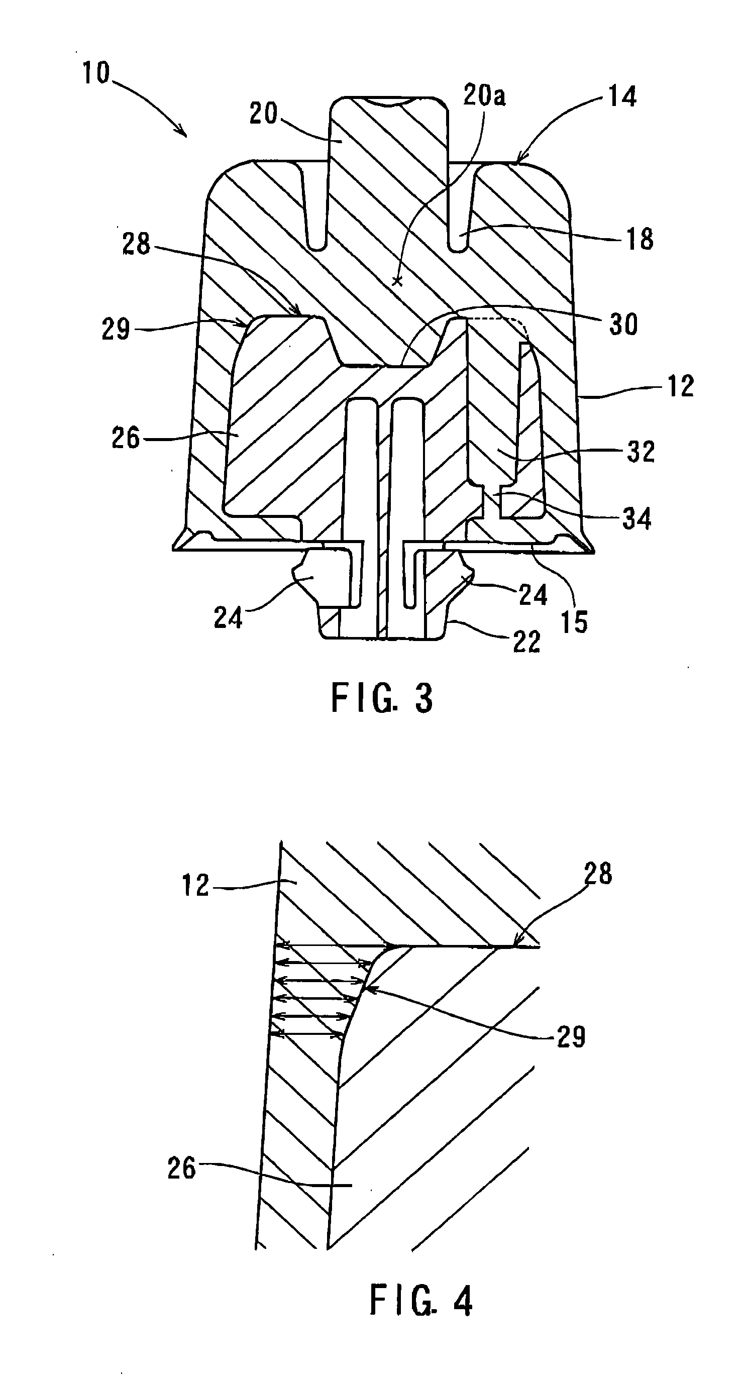
[0021]A representative cushion clip 10 is shown in FIGS. 1 to 4. The cushion clip 10 is intended to be attached to a vehicle body 36 (a fixed member) in order to receive a load of a vehicle slide door 38 (a movable member) and to absorb impact caused by the load thereof. As best shown in FIG. 1, a representative cushion clip 10 includes a cushioning portion 12 made of a soft material such as a thermoplastic elastomer (TPE), an attachment portion 22 made of a hard material such as polypropylene (PP), and a connecting portion 26 integrally formed with the attachment portion 22. The connecting portion 26 is embedded (received) in the cushioning portion 12, so that the cushioning portion 12 can be integrated with th...


PUM


Abstract

A cushion clip may include a cushioning portion made of a soft material and capable of being elastically deformed when a compression force is applied thereto, an attachment portion made of a hard material, and a connecting portion integrally formed with the attachment portion. The connecting portion is embedded in the cushioning portion such that the cushioning portion can be integrated with the attachment portion. A portion of the cushioning portion surrounding an outer circumferential periphery of an end surface of the connecting portion has a lateral thickness that is varied in a direction in which the compression force is applied to the cushioning portion.

Description

BACKGROUND OF THE INVENTION[0001]1. Field of the Invention[0002]The present invention relates to a cushion clip that is used in a vehicle. More particularly, the present invention relates to a cushion clip that is attached to a fixed member (e.g., a vehicle body) in order to receive a load of a movable member (e.g., a vehicle slide door) and to absorb impact caused thereby.[0003]2. Description of Related Art[0004]A known cushion clip of this type is taught by, for example, Japanese Laid-Open Patent Publication Number 2008-196651. The cushion clip has a cushioning portion made of a soft material such as a thermoplastic elastomer (TPE), an attachment portion made of a hard material such as polypropylene (PP), and a connecting portion integrally formed with the attachment portion. The connecting portion is embedded (received) in the cushioning portion such that the cushioning portion can be integrated with the attachment portion. The attachment portion is inserted into an attachment ho...

Claims


Application Information

Patent Timeline
IPC IPC(8): F16B2/22
CPCF16B21/086F16F1/371Y10T24/44026Y10T24/44017Y10T16/628E05F5/022
Inventor SUGIYAMA, TAKAHIRO
Owner DAIWA KASEI IND CO LTD
Why Eureka
Try Eureka