Clamping device for a saw blade

Inactive Publication Date: 2011-11-24
CHERVON HK LTD WANCHAI
View PDF13 Cites 4 Cited by
  • Summary
  • Abstract
  • Description
  • Claims
  • Application Information

AI Technical Summary

Benefits of technology

[0007]The present application further provides a method of installing and clamping the saw blades by using the clamping device for a saw blade. First, the first locking means is driven to move relative to the main body and away from the longitudinal axis of the saw blade slot. The second locking element is driven to move relative to the main body and away from the longitudinal axis of the saw blade slot. The clamped portion of the saw is inserted into the saw blade slot and the firs

Problems solved by technology

However, the mechanism merely limits the swing of the saw blade to some extent, and the saw blade could still have some swing in the direction perpendicu

Method used


Image

  • Clamping device for a saw blade
  • Clamping device for a saw blade
  • Clamping device for a saw blade

Examples


Example

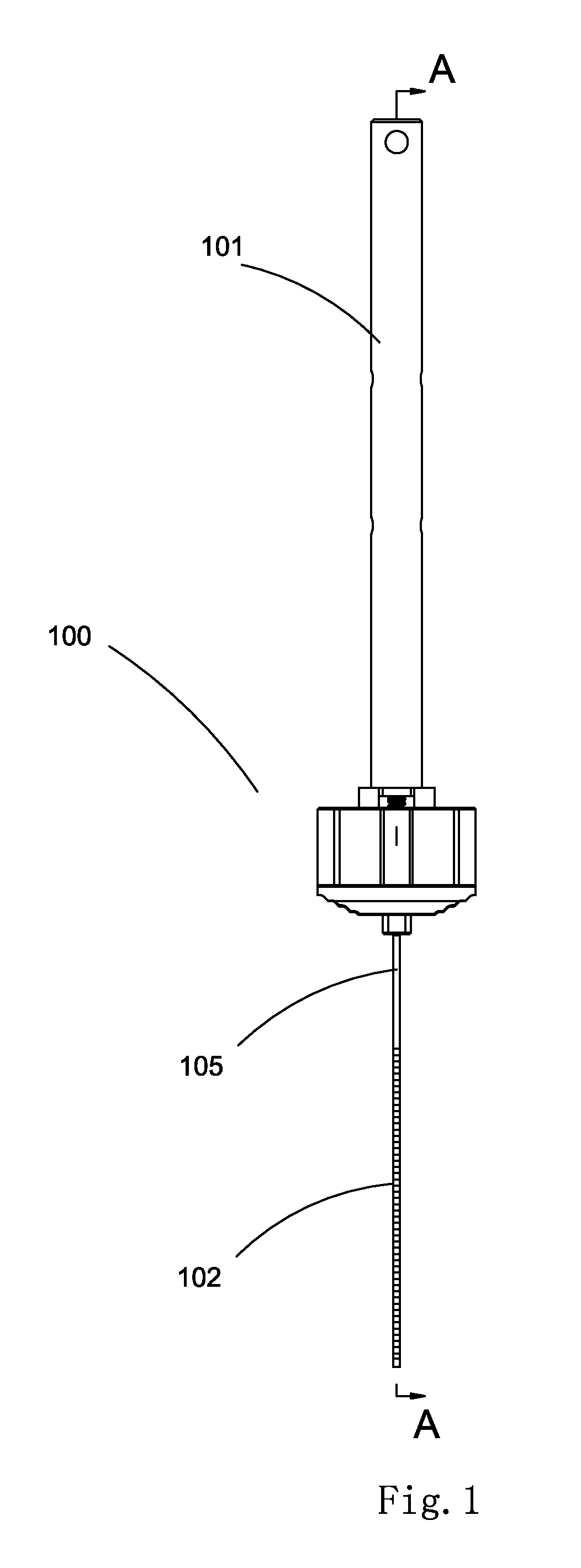
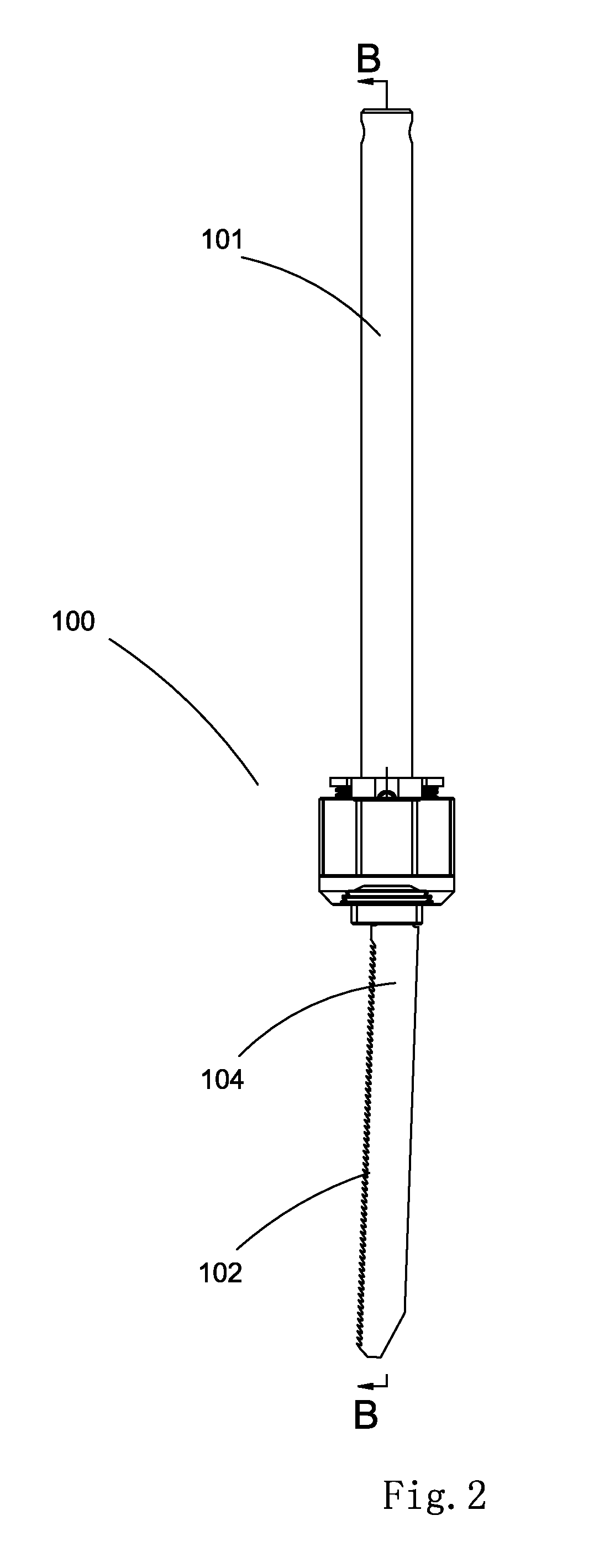
[0017]As shown in FIGS. 1-2, the clamping device for a saw blade 100 of the present application is fixedly installed to the reciprocating rod 101 of the reciprocating saw (not shown) via a pin 103. The clamped portion 108 of the saw blade 102 is installed into the clamping device for a saw blade 100, and the clamped portion 108 of the saw blade 102 has a wide face 104 and a narrow face 105.

[0018]As shown in FIGS. 2-7, the clamping device for a saw blade 100 further comprises a main body 1, in which a saw blade slot 2 for receiving the saw blade is formed. The saw blade slot 2 has a longitudinal axis X, and the clamped portion 108 of the saw blade 102 can be inserted into the saw blade slot 2. The main body 1 comprises a first side wall 106 and an adjacent second side wall 107. A first slot is formed on the first side wall 106. The first slot is preferably an inclined slot 3, which is formed with a certain angle with respect to the extending direction of the longitudinal axis X of th...


PUM

PropertyMeasurementUnit
Forceaaaaaaaaaa
Efficiencyaaaaaaaaaa

Abstract

The present application provides a clamping device for a saw blade having a main body with a saw blade slot for installing the clamped portion of the saw blade, a first locking element installed on the main body and a first reversion element for exerting a force on the first locking element. The clamping device for a saw blade may further comprise a second locking element installed on the main body having a second reversion element for exerting a force on the second locking element so that the second locking element tends to move toward the longitudinal axis of the saw blade slot. At the clamping location, the first and second locking elements clamp the saw blade. Using the saw blade clamping device of the present application results in a stable saw blade for sawing and greatly enhances sawing efficiency.

Description

CROSS-REFERENCE TO RELATED APPLICATIONS[0001]This application claims priority to CN 201010178036.0, filed May 18, 2010, which is hereby incorporated by reference.FEDERALLY SPONSORED RESEARCH OR DEVELOPMENT[0002]Not Applicable.TECHNICAL FIELD[0003]The invention relates to a clamping device for a saw blade, in particular, to a clamping device for the saw blade of a reciprocating saw.BACKGROUND OF THE INVENTION[0004]For clamping a saw blade on a reciprocating saw, there are various prior methods for clamping devices known to those in the market. The current devices for clamping a saw blade only allow for the wide face or the narrow face of the saw blade to be clamped by the clamping device. For example, U.S. Pat. No. 6,101,726 discloses a clamping device for a saw blade that clamps the narrow face of the saw blade, wherein a V-shaped slot is formed on the clamping element to ensure clamping the saw blade stably, and the swing of the saw blade in a direction perpendicular to the wide fa...

Claims


Application Information

Patent Timeline
IPC IPC(8): B26D7/26B23P11/00
CPCY10T29/49826B23D51/10Y10T83/9457B23D49/08
Inventor ZHOU, HONGTAO
Owner CHERVON HK LTD WANCHAI
Why Eureka
Try Eureka