Run flat tire

a technology of run-flat tires and crown portions, which is applied in the direction of pneumatic tyre reinforcements, tire beads, vehicle components, etc., can solve the problems of tire breakdown, limited degree of excellent run-flat durability that can be guaranteed, and tire breakdown, etc., to achieve excellent steering stability, improve the stiffness of the crown portion, and improve the effect of riding comfor

Inactive Publication Date: 2011-11-24
THE YOKOHAMA RUBBER CO LTD
View PDF4 Cites 11 Cited by
  • Summary
  • Abstract
  • Description
  • Claims
  • Application Information

AI Technical Summary

Benefits of technology

[0014]With the present technology, the second carcass layer having the end that does not reach the outer peripheral surface of the bead core is disposed along the outer peripheral surface of the carcass layer. Therefore, the second carcass layer, which is freed from shearing strain caused by tension applied to the carcass layer, enhances the stiffness of the crown portion. This results in excellent steering stability and riding comfort being displayed when regular traveling and also makes possible the enhancement of run flat durability by suppressing buckling of the tread portion when run-flat traveling.
[0015]Moreover, the outer peripheral edge of the bead filler is positioned more to the inward side in the tire radial direction than the line X normal to the rim line. Therefore, the outer peripheral edge of the bead filler is distanced from the region prone to being subjected to the large amount of stress caused by contact pressure with the rim when run-flat traveling. Thus, shearing stress acting on the end of the bead filler can be suppressed and run-flat durability can be enhanced due to separation of the rubber in this area being suppressed.
[0016]Additionally, the relationship between the rubber thickness Ga, taken on the line X normal to the rim line between the carcass layer and the outer wall surface of the side wall portion, and the maximum rubber thickness Gb, taken on the line normal second carcass layer between the second carcass layer and the outer wall surface of the side wall portion, is set within a predetermined range; and a ratio of variation in the rubber thickness in the tire radial direction on the outer side of the carcass layer is restricted. As a result, localized, concentrated stress caused by contact pressure with the rim is mitigated, which leads to separation breakdowns of the rubber near the rim cushion being suppressed when run-flat traveling and, at the same time, rubber thickness in the upper region of the bead portion being ensured. Therefore, riding comfort when regular traveling can be enhanced.
[0017]Furthermore, a large rubber thickness Gc taken on the line X normal to the rim line between the carcass layer and the tire inner wall surface is ensured, and the rubber thickness Gc is set so as to be close to the rubber thickness Ga described above. As a result, it is possible to mitigate shearing stress acting between the carcass layer and the second carcass layer, which leads to separation breakdowns therebetween being suppressed. Particularly, durability when run-flat traveling can be enhanced, and, at the same time, riding comfort during regular traveling can be enhanced due to rubber thickness being maintained in regions where great deformation occurs due to input from the rim.
[0018]Additionally, the folded up end of the carcass layer is disposed in the vicinity of a position where the rubber thickness between the outer wall surfaces of the side wall portions reaches a maximum. Therefore, separation breakdowns from the folded up end of the carcass layer are suppressed and, particularly, durability when run-flat traveling can be enhanced.

Problems solved by technology

However, when only these sorts of technologies are applied there are problems in that the degree of excellent run flat durability that can be ensured is limited and riding comfort when regular traveling is significantly worsened due to the increase in side wall stiffness.
Particularly, when the tire cross-sectional height reaches a certain height, tire breakdowns when run-flat traveling consist mainly of breakdowns in the vicinity of the rim cushion near the bead portion.
However, both of these proposals are limited as to effectiveness in enhancing run-flat durability, and, at the same time, do not directly lead to improvements in the effectiveness of enhancing riding comfort when regular traveling.
Therefore, neither provides technology that can sufficiently satisfy the demand for both run-flat durability and riding comfort.
Therefore, the outer peripheral edge of the bead filler is distanced from the region prone to being subjected to the large amount of stress caused by contact pressure with the rim when run-flat traveling.

Method used


Image

  • Run flat tire
  • Run flat tire
  • Run flat tire

Examples


example , working examples 1 and 2

Conventional Example, Working Examples 1 and 2, Comparative Examples 1 and 2

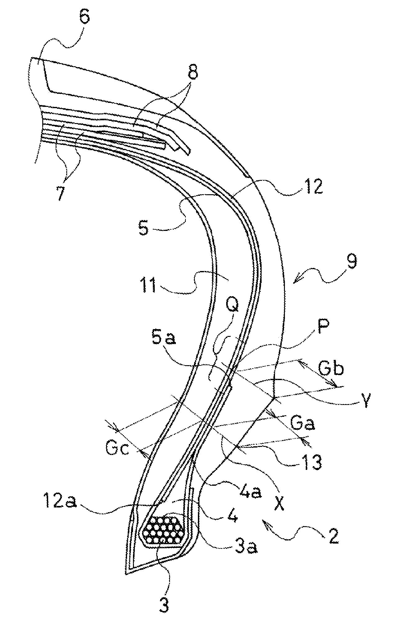
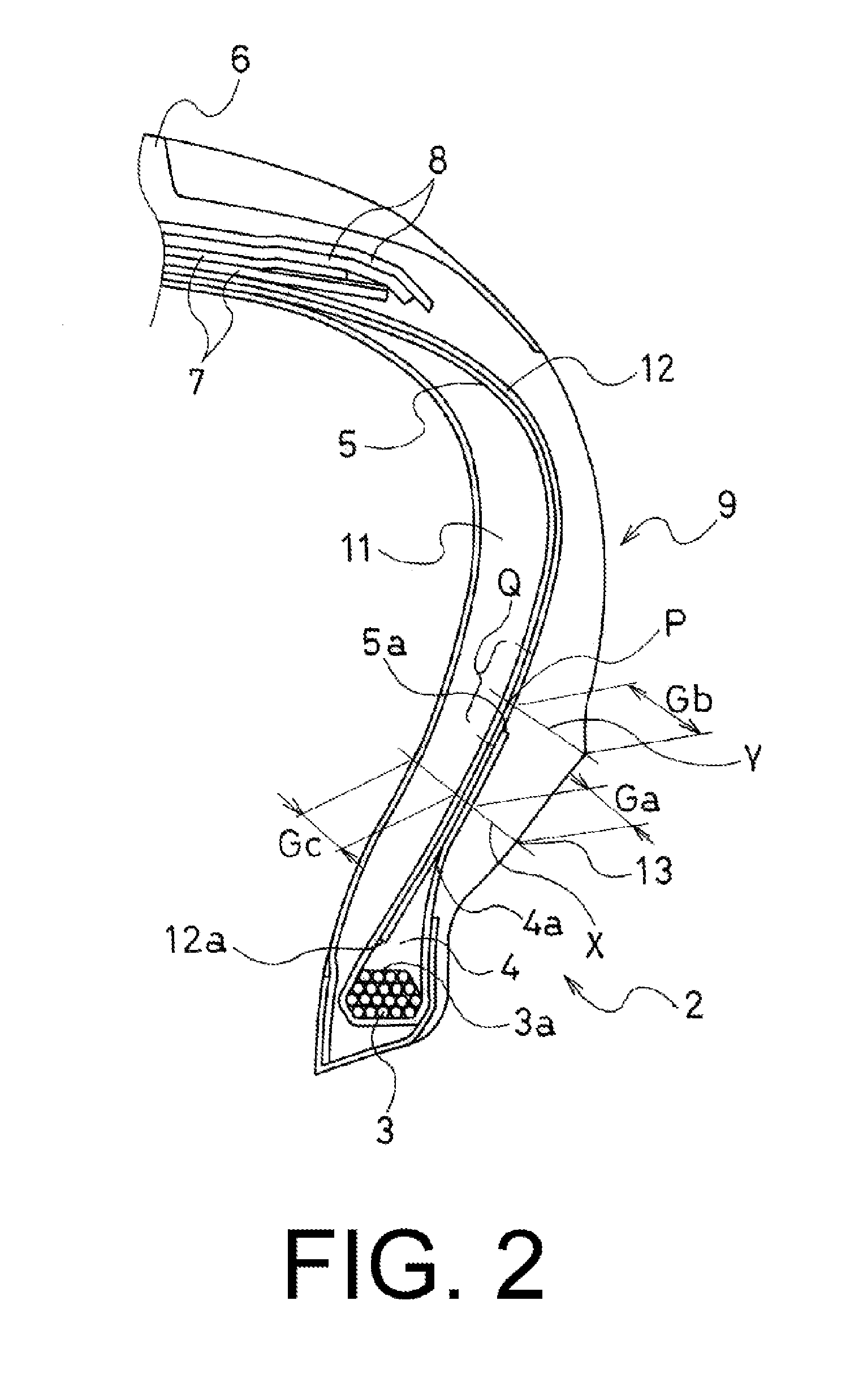
[0043]A conventional tire (Conventional Example), present technology tires (Working Examples 1 and 2), and comparative tires (Comparative Examples 1 and 2) were manufactured having a common tire size of 245 / 45R17 and a basic construction of the left and right side wall portions as illustrated in FIG. 2. The presence / absence of the second carcass layer 12, position of the outer peripheral edge 4a of the bead filler 4, rubber thicknesses Ga, Gb, and Gc in the upper region of the bead portion 2, and the position of the folded up end 5a of the carcass layer 5 were each varied as shown in Table 1.

[0044]These five types of tires were each mounted on the front and rear wheels of a front-engine front-wheel drive (FF) vehicle having an engine displacement of 1,800 cc. Run-flat durability and riding comfort were evaluated via the test methods described below.

[0045]Note that in each of the tires, rayon fiber cord was u...

working example 3

[0049]The side reinforcing layers 11,11 in the tire of Working Example 1 described above, as shown in Table 2, were fabricated from the inner side rubber 11a and the outer side rubber 11b that are connected in the tire radial direction and that have different JIS-A hardnesses to manufacture a tire of Working Example 3 of the present technology. Here, cross-sectional areas of the inner side rubber 11a and the outer side rubber 11b were equivalent.

[0050]For this tire, evaluations of run-flat durability and riding comfort were performed using the same test methods described above, and the results thereof, along with the results of the Conventional Example shown in Table 1, were recorded in Table 2.

TABLE 2ConventionalWorkingExampleExample 3JIS-A rubberInner side rubber8085hardness of the side11areinforcing layer 11Outer side rubber807511bEvaluation ResultsRun-flat durability100110Riding comfort34.7

[0051]It is evident from Table 2 that, compared to the tire of the Conventional Example, t...

working example 4

[0052]The folded up end 5a of the carcass layer 5 in the tire of Working Example 1 described above, as shown in Table 3, was configured to extend to the inner side of the edge of the belt layer 7 in one of the side wall portions 9, and was also configured so that the carcass layer 5 and the edge of the belt layer 7 overlapped 5 mm. Thus, a tire of Working Example 4 of the present technology was manufactured.

[0053]For this tire, evaluations of run-flat durability and riding comfort were performed using the same test methods described above, and the results thereof, along with the results of the Conventional Example shown in Table 1, were recorded in Table 3.

TABLE 3ConventionalWorkingExampleExample 4Position of the folded up end 5aLower side of PUnder the edge ofof the carcass layer 545 mmthe belt layer 7(5 mm overlap)EvaluationRun-flat durability100110ResultsRiding comfort33.7

[0054]It is evident from Table 3 that, compared to the tire of the Conventional Example, the tire of the Work...


PUM

PropertyMeasurementUnit
thicknessaaaaaaaaaa
thicknessaaaaaaaaaa
speedaaaaaaaaaa

Abstract

A side wall reinforced run flat tire, wherein a second carcass layer that does not reach a bead core is disposed along the outer peripheral surface of a carcass layer. A position of an outer peripheral edge of a bead filler, a relationship between a rubber thickness Gc of the inner side and a rubber thickness Ga of an outer side taken on the line X normal to the rim line and centered on the carcass layer, a relationship between the rubber thicknesses Ga and Gb of the side wall rubber in an upper region of a bead portion, and a position of a folded up end of the carcass layer are each stipulated.

Description

PRIORITY CLAIM[0001]Priority is claimed to Japan Patent Application Serial No. 2010-116967 filed on May 21, 2010.BACKGROUND[0002]1. Technical Field[0003]The present technology relates to a run flat tire, and particularly relates to a run flat tire configured so as to have both durability when run-flat traveling and riding comfort when regular traveling.[0004]2. Related Art[0005]In run flat tires provided with a side reinforcing layer having a falcated cross-section on an inner surface side of a side wall portion, methods such as increasing a thickness of the side reinforcing layer and using a rubber with a high hardness have been used in order to ensure durability when run-flat traveling. However, when only these sorts of technologies are applied there are problems in that the degree of excellent run flat durability that can be ensured is limited and riding comfort when regular traveling is significantly worsened due to the increase in side wall stiffness.[0006]Particularly, when th...

Claims


Application Information

Patent Timeline
Patent Type & Authority Applications(United States)
IPC IPC(8): B60C17/00
CPCB60C15/0018B60C15/0045B60C17/0009B60C2017/0072B60C2017/0063B60C2013/006Y10T152/10819B60C2009/2252B60C9/005B60C15/00B60C15/0009B60C17/0027Y10T152/10837B60C2013/007
Inventor HORIUCHI, KENJI
Owner THE YOKOHAMA RUBBER CO LTD
Why Eureka
Try Eureka