
Side airbag system and method of manufacturing side airbag

a technology of side airbags and airbags, which is applied in the direction of hand sewing, vehicle components, textiles and paper, etc., can solve the problems of difficult to set an appropriate internal pressure for each chamber, complicated sewing separation panels, and difficulty in sewing. sew, improve mass productivity, and improve air tightness

Active Publication Date: 2011-11-24
TOYOTA JIDOSHA KK
View PDF6 Cites 41 Cited by
  • Summary
  • Abstract
  • Description
  • Claims
  • Application Information

AI Technical Summary

Benefits of technology

The invention provides a side airbag system with a partitioned upper and lower bag portion that improves mass productivity and airtightness between the two parts. The system includes a tube that extends through the partition and is sewn to the upper and lower bag portions. The tube is formed into a cylindrical shape and has an opening at one end located adjacent to the lower bag portion and at the other end located adjacent to the upper bag portion. The tube is sewn to the lower bag portion and the upper bag portion at the lower ends, and the upper bag portion covers at least one of the chest and shoulder of the occupant and the lower bag portion covers the hip of the occupant. The system also includes an inflator that is arranged inside the tube and is supplied with inflation gas to inflate and deploy the airbag in the event of a side impact crash.

Problems solved by technology

Such work for sewing the separation panel is complicated, so there is room for improvement in terms of mass production of airbags.
However, with the above structure, it is difficult to maintain airtightness between the upper chamber and the lower chamber, so it is presumably difficult to set an appropriate internal pressure for each chamber.

Method used


Image

  • Side airbag system and method of manufacturing side airbag
  • Side airbag system and method of manufacturing side airbag
  • Side airbag system and method of manufacturing side airbag

Examples


Embodiment Construction

[0091]Hereinafter, embodiments of the invention will be described with reference to the accompanying drawings.

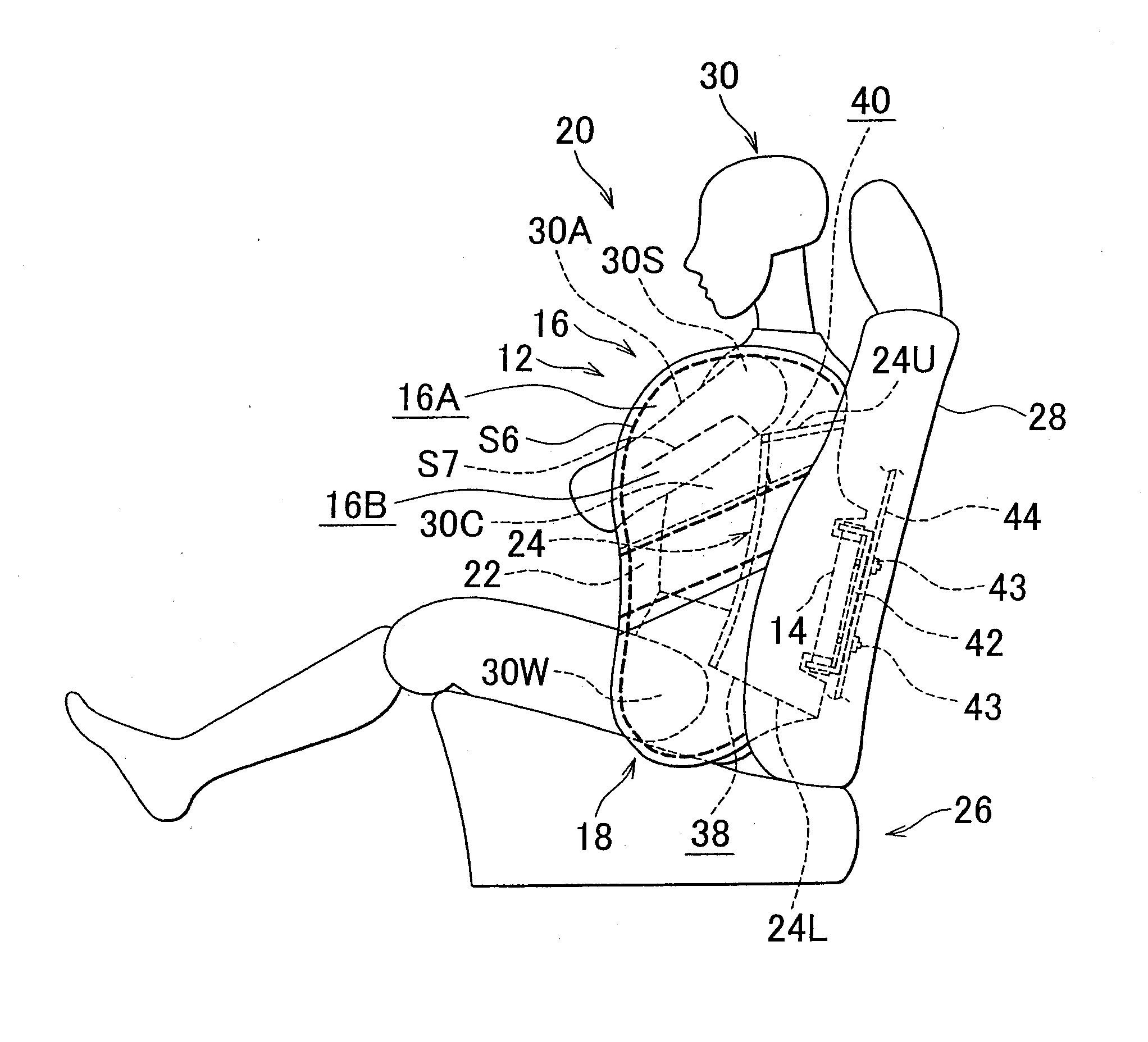
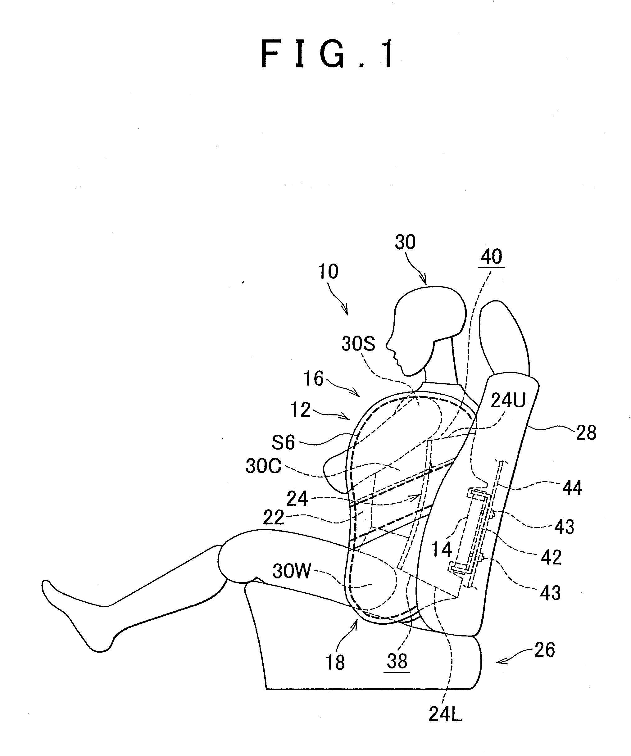
[0092]First, a side airbag system according to a first embodiment of the invention will be described. As shown in FIG. 1, the side airbag system 10 according to the first embodiment of the invention includes a side airbag 12 and an inflator 14.

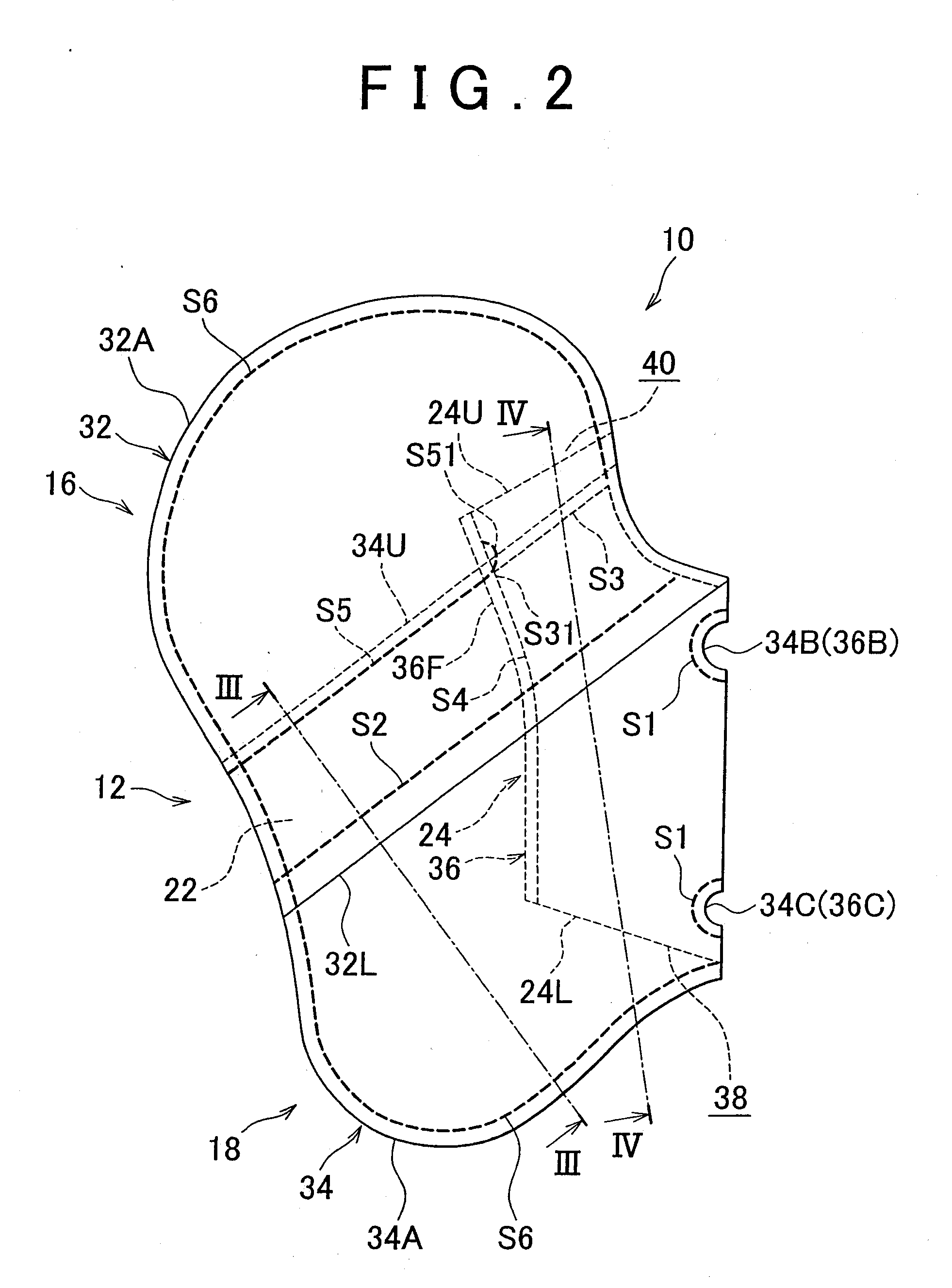
[0093]As shown in FIG. 2, the side airbag 12 has an upper bag portion 16, a lower bag portion 18, a tether portion 22 and a tube 24. As shown in FIG. 1, the side airbag 12 is, for example, folded and accommodated in the side portion of a seat back 28 in a vehicle seat 26 during normal times. In the event of a side impact crash, the side airbag 12 is supplied with gas from the inflator 14 to inflate and deploy to the lateral side of an occupant 30 seated on the vehicle seat 26. Note that FIG. 1 shows a dummy as the occupant 30.

[0094]The upper bag portion 16 is formed of pieces of upper base fabric 32, and is an inflatable portion locate...


PUM


Abstract

In a side airbag system (10), a tether portion (22), which serves as a partition between an upper bag portion (16) and a lower bag portion (18), is formed of upper regions (34U) of a piece of lower base fabric (34), and is formed by sewing the upper regions (34U) of the lower base fabric (34), folded toward a vehicle front side along a fold axis, together. In addition, a tube (24) that distributes inflation gas between the upper bag portion (16) and the lower bag portion (18) extends through the tether portion (22) to the lower bag portion (18) and to the upper bag portion (16). The tube (24) is formed into a cylindrical shape in such a manner that a piece of tube base fabric (36) is sewed to the upper regions (34U) of the lower base fabric (34) and folded toward a vehicle front side along the fold axis and then front ends (36F) of the folded tube base fabric are sewed together in a tube longitudinal direction.

Description

BACKGROUND OF THE INVENTION[0001]1. Field of the Invention[0002]The invention relates to a side airbag system and a method of manufacturing a side airbag.[0003]2. Description of the Related Art[0004]For example, Published Japanese Translation of PCT Application No. 2003-501303 (JP-A-2003-501303) describes a side airbag. The side airbag includes a cushion and an inflatable tube. The cushion has an inflatable upper chamber and an inflatable lower chamber that are partitioned by a separation panel. The inflatable tube is located adjacent to the cushion and is arranged adjacent to one of a bottom and rear side of the cushion so as to extend the range of at least part of the cushion before the cushion completely inflates by inflation gas.[0005]However, the separation panel described in JP-A-2003-501303 is separately formed from the pieces of base fabric of the airbag, and the peripheral edge of the separation panel is sewed to the two pieces of airbag base fabric. Such work for sewing th...

Claims


Application Information

Patent Timeline
Patent Type & Authority Applications(United States)
IPC IPC(8): B60R21/16D05B97/00B60R21/20B60R21/207B60R21/233B60R21/2338B60R21/239B60R21/261
CPCB60R21/23138B60R21/2346B60R2021/23324B60R2021/23316B60R2021/23146
Inventor YAMAMOTO, KAZUHITOTAKAGAWA, MASANORI
Owner TOYOTA JIDOSHA KK
Learn More