Rectifier-free Piezoelectric Energy Harverster and Battery Charger

a piezoelectric energy harverster and battery charger technology, applied in the direction of electric generator control, machines/engines, generators/motors, etc., can solve the problems of system energy waste, zinc oxide crystal generation of charge imbalance, and difficulty in replacing or recharging batteries

Inactive Publication Date: 2011-11-24
GEORGIA TECH RES CORP
View PDF6 Cites 26 Cited by
  • Summary
  • Abstract
  • Description
  • Claims
  • Application Information

AI Technical Summary

Benefits of technology

[0015]In another aspect, the invention is a circuit for harvesting electrical energy that includes an alternating current source that is coupled between a first note and a second node. A load is coupled between a fifth node and the second node. An inductor, coupled between a third node and a fourth node, is configured to store electrical energy. A first switch is coupled between the first node and the third node. A second switch is coupled between the fourth node and the second node. A first unidirectional current directing device is coupled between the third node and the fifth node and is configured to allow current to flow onl

Problems solved by technology

However, in certain applications, such as biomedical implants, replacing or recharging batteries may be difficult and costly.
For example, a zinc oxide crystal will generate a charge imbalance when subjected to a bending force.
However, most batteries require direct current to be recharged.
Such a system tends to waste a considerable amount of energy.
The problem is rectifying unpredictably small ac signals (which are prevalent in small volumes and with weak vibrations whose peak voltages fall below the rectified output level targeted, requires low-loss, no-threshold rectifiers.
Miniaturized mobile electronic systems, such as biomedical drug-delivery implants, acceleration-monitoring and pressure-monitoring sensors, and micro-sensor nodes in wireless networks, have so little space for energy storage that they suffer from short operational lives.
Unfortunately, replacing easily exhaustible onboard batteries is prohibitive because the systems often conduct in situ measurements in unreachable places and operate in concert with numerous other devices, w

Method used


Image

  • Rectifier-free Piezoelectric Energy Harverster and Battery Charger
  • Rectifier-free Piezoelectric Energy Harverster and Battery Charger
  • Rectifier-free Piezoelectric Energy Harverster and Battery Charger

Examples


Embodiment Construction

[0024]A preferred embodiment of the invention is now described in detail. Referring to the drawings, like numbers indicate like parts throughout the views. Unless otherwise specifically indicated in the disclosure that follows, the drawings are not necessarily drawn to scale. As used in the description herein and throughout the claims, the following terms take the meanings explicitly associated herein, unless the context clearly dictates otherwise: the meaning of “a,”“an,” and “the” includes plural reference, the meaning of “in” includes “in” and “on.”

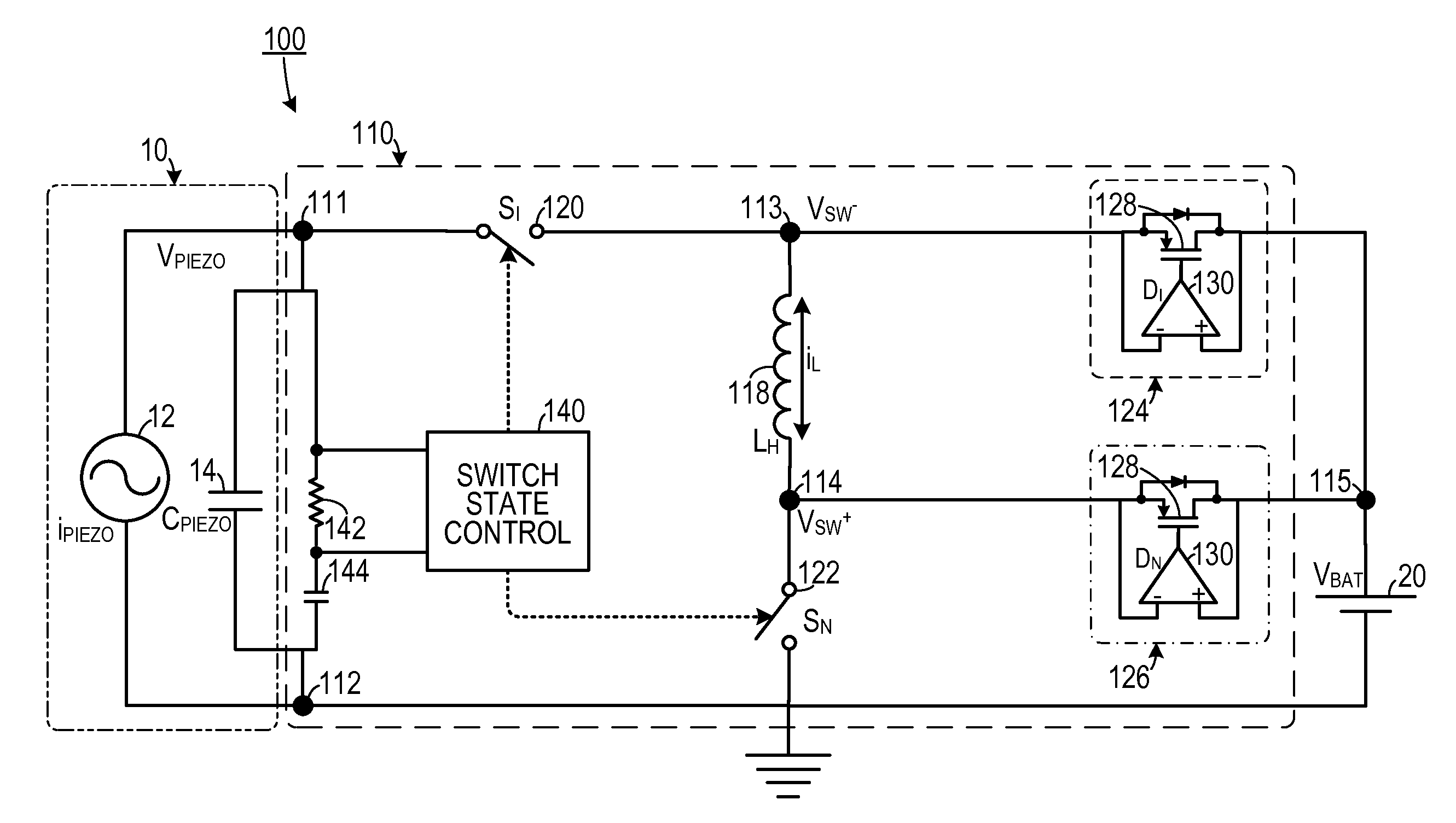
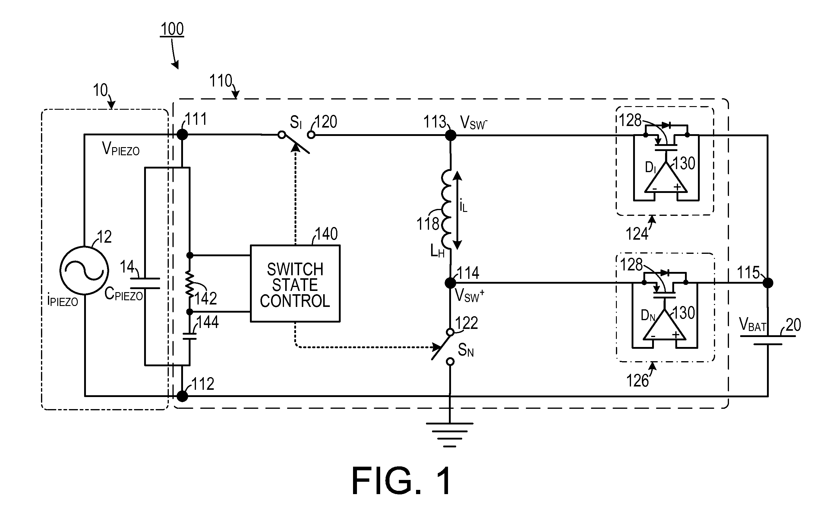
[0025]As shown in FIG. 1, one embodiment of a circuit 100 for harvesting electrical energy from a piezoelectric source 10 (which can include a piezoelectric structure 12 and an inherent capacitance 14), or other type of alternating current source, and for storing the electrical energy in a battery 20, or other type of load, includes an inductor 118 that stores electrical energy from the piezoelectric source 10. A diode bridge-free swit...


PUM


Abstract

A circuit for harvesting electrical energy from a piezoelectric source and for storing the electrical energy in a battery includes an inductor that is configured to store electrical energy. A diode bridge-free switching network is configured to: direct electrical energy from the piezoelectric source to the inductor during a first portion of a piezoelectric charge generating cycle; and direct electrical energy from the inductor to the battery during a second portion of the piezoelectric charge generating cycle.

Description

CROSS-REFERENCE TO RELATED APPLICATION(S)[0001]This application claims the benefit of U.S. Provisional Patent Application Ser. No. 61 / 345,770, filed May 18, 2010, the entirety of which is hereby incorporated herein by reference.BACKGROUND OF THE INVENTION[0002]1. Field of the Invention[0003]The present invention relates to electrical energy harvesting systems and, more specifically, to an electrical energy harvesting system that is rectifier free.[0004]2. Description of the Related Art[0005]Microscale and nanoscale integrated devices are used in a variety of applications, including in biomedical implants and sensors. Many such devices are powered by electrical energy. Conventional power sources, such as electrochemical batteries, are often used to power such integrated devices. However, in certain applications, such as biomedical implants, replacing or recharging batteries may be difficult and costly. One approach to recharging such batteries is to harvest electrical energy from pie...

Claims


Application Information

Patent Timeline
IPC IPC(8): F03G7/08
CPCF03G7/08H02N2/186H02N2/181H02M7/219
Inventor KWON, DONGWONRINCON-MORA, GABRIEL ALFONSO
Owner GEORGIA TECH RES CORP
Why Eureka
Try Eureka