3D camera and imaging method

a 3d camera and imaging method technology, applied in the field of 3d cameras and imaging methods, can solve the problems of difficult scaling down to the domestic camera market, high cost of broadcast and cinema quality 3d camera systems,

Active Publication Date: 2011-11-24
SONY COMPUTER ENTERTAINMENT INC
View PDF3 Cites 34 Cited by
  • Summary
  • Abstract
  • Description
  • Claims
  • Application Information

AI Technical Summary

Benefits of technology

[0008]In a first aspect of the present invention, a 3D camera comprises first and second laterally displaced optical imaging systems each comprising one or more lenses, the first and second optical imaging systems also each comprising one or more actuators arranged to move one or more lenses of the respective optical imaging system, and a digital image analyser arranged in operation to evaluate the respective field of view of a first and second image of a stereoscopic image pair obtained...

Problems solved by technology

Broadcast and cinema quality 3D camera systems are very expensive, and rely on sophisticated (and heavy) optics...

Method used


Image

  • 3D camera and imaging method
  • 3D camera and imaging method
  • 3D camera and imaging method

Examples


Embodiment Construction

[0021]A 3D camera and an imaging method are disclosed. In the following description, a number of specific details are presented in order to provide a thorough understanding of the to embodiments of the present invention. It will be apparent, however, to a person skilled in the art that these specific details need not be employed to practise the present invention. Conversely, specific details known to the person skilled in the art are omitted for the purposes of clarity where appropriate.

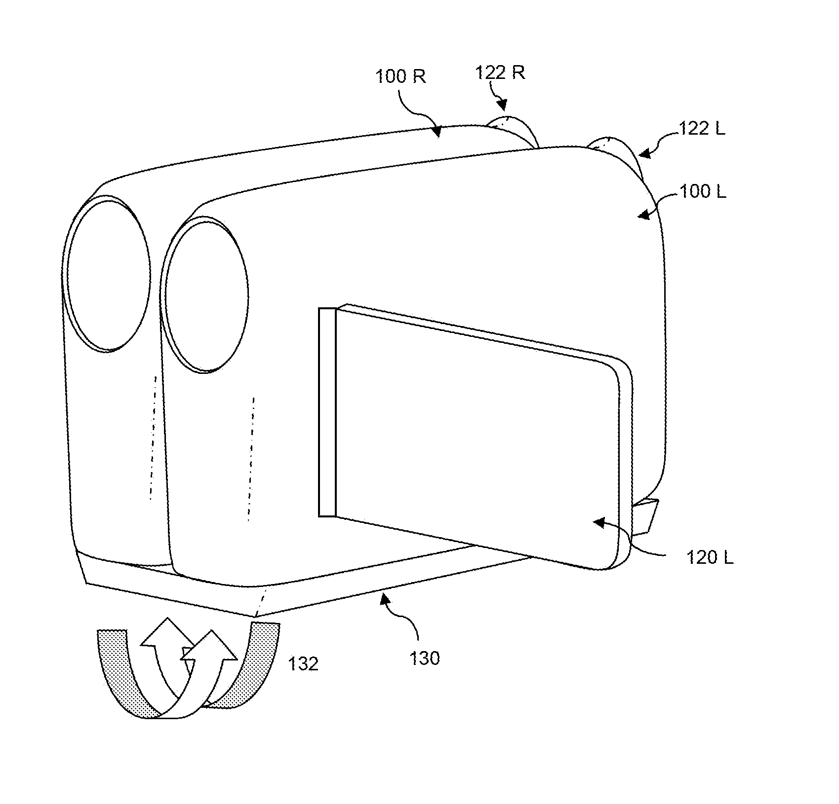
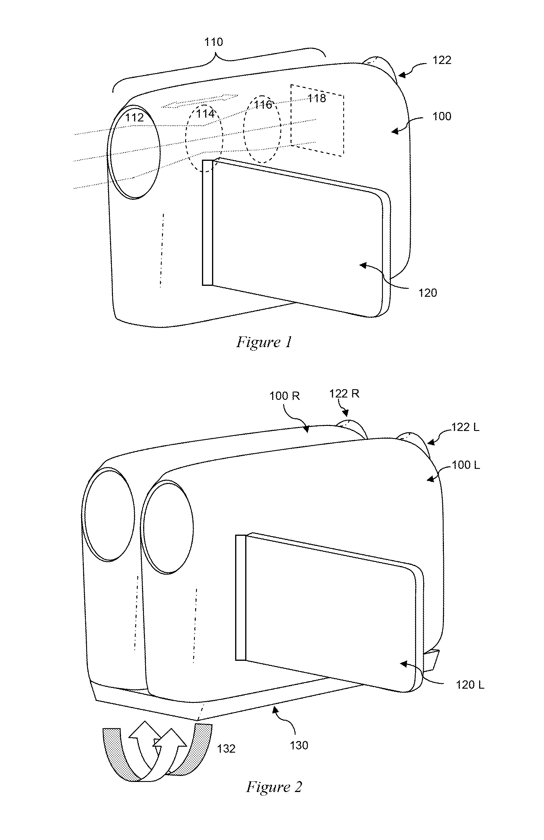
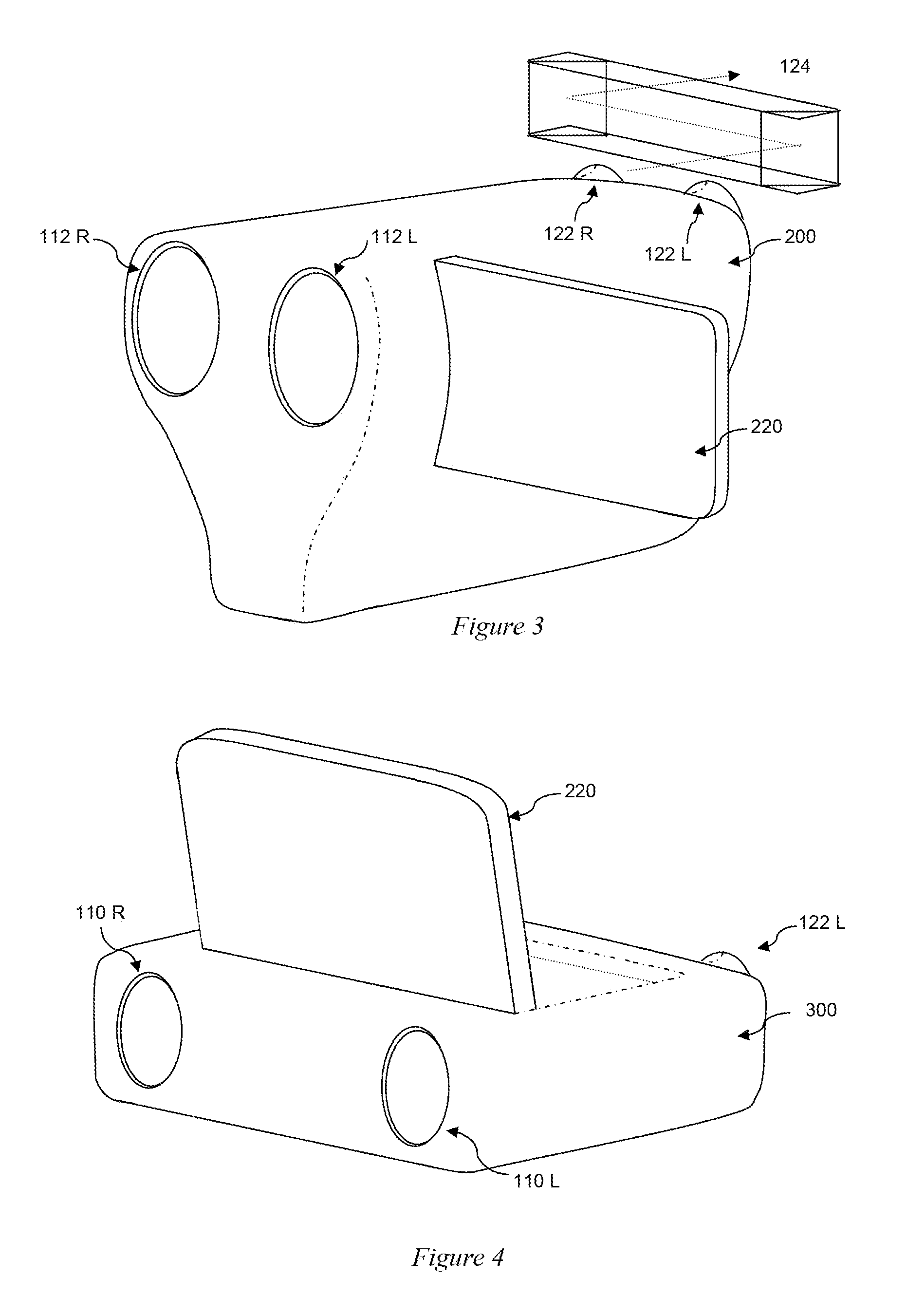
[0022]In an example embodiment of the present invention, the optical imaging systems of two conventional cameras (e.g. conventional camcorders) are housed in a common housing of a 3D camera system (see for example FIG. 3). The left and right-mounted optical imaging systems each separately comprise respective lens assemblies (collectively referred to as a lens), an image sensor, and focus and zoom actuators.

[0023]The respective left and right images captured by the left and right image sensors are the...


PUM


Abstract

A 3D camera comprises first and second laterally displaced optical imaging systems each comprising one or more lenses. The optical imaging systems also each comprise one or more actuators arranged to move one or more lenses of the respective optical imaging system, and a digital image analyser configured to evaluate the respective field of view of first and second images of a stereoscopic image pair obtained respectively from the first and second optical imaging systems and to generate a disparity value based on a disparity between the respective fields of view. The 3D camera is arranged in operation to adjust the field of view of one or more images generated by the first and second optical imaging systems responsive to the disparity value so as to reduce the disparity between the respective fields of view of stereoscopic image pairs obtained from the first and second optical imaging systems.

Description

BACKGROUND OF THE INVENTION[0001]1. Field of the Invention[0002]The present invention relates to a 3D camera and imaging method.[0003]2. Description of the Prior Art[0004]The anticipated uptake of 3D televisions in the home can be expected to create a market in 3D cameras for domestic use (e.g. still and video cameras and camcorders), in much the same way that HD televisions have created a market for HD cameras.[0005]Broadcast and cinema quality 3D camera systems are very expensive, and rely on sophisticated (and heavy) optics to achieve their 3D effects; consequently this technology is not easily scalable down to the domestic camera market.[0006]Therefore it is desirable to develop a 3D camera that provides normal camera functions, such as a zoom function, whilst being economically and practically feasible.[0007]The present invention seeks to address or mitigate the above problem.SUMMARY OF THE INVENTION[0008]In a first aspect of the present invention, a 3D camera comprises first a...

Claims


Application Information

Patent Timeline
IPC IPC(8): H04N13/02H04N13/239
CPCH04N13/0246H04N13/0239H04N13/239H04N13/246
Inventor BICKERSTAFF, IANBENSON, SIMONKERSHAW, NIGELHOCKING, IAN MICHAEL
Owner SONY COMPUTER ENTERTAINMENT INC
Why Eureka
Try Eureka