Calendar mechanism and timepiece equipped with the same

a technology of a calendar mechanism and a timepiece, which is applied in the direction of horological winding mechanisms, instruments, horological winding mechanisms, etc., can solve the problems of avoiding the inevitable design of the component, avoiding the fear of the component cost becoming too high to neglect, etc., and achieve the effect of reducing the torque load

Inactive Publication Date: 2011-11-24
SEIKO INSTR INC
View PDF5 Cites 7 Cited by
  • Summary
  • Abstract
  • Description
  • Claims
  • Application Information

AI Technical Summary

Benefits of technology

[0010]It is an aspect of the present application to provide a calendar mechanism capable of reducing a torque load due to a spring portion of a jumper while keeping a minimum occupation area, and a timepiece equipped with such a calendar mechanism.

Problems solved by technology

Further, since the spring mechanism 111 assumes a complicated configuration and arrangement, a rather bothersome design is inevitable.
Further, the distance (arm length) between the cam contact portion constituting the cam follower and the lever spring shaft 112 and the distance (arm length) between the jump control lever contact portion 111c and the lever spring shaft 112 is inevitably approximately the same, so that the protruding and recessed configuration of the cam portion cannot but be small, and there is a fear of the component cost becoming too high to neglect.

Method used


Image

  • Calendar mechanism and timepiece equipped with the same
  • Calendar mechanism and timepiece equipped with the same
  • Calendar mechanism and timepiece equipped with the same

Examples


embodiment

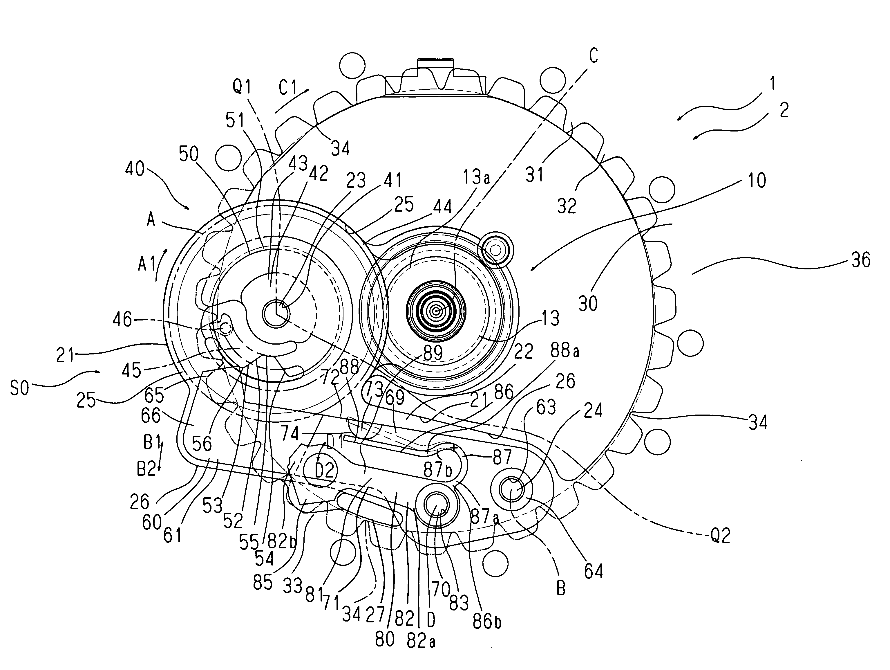
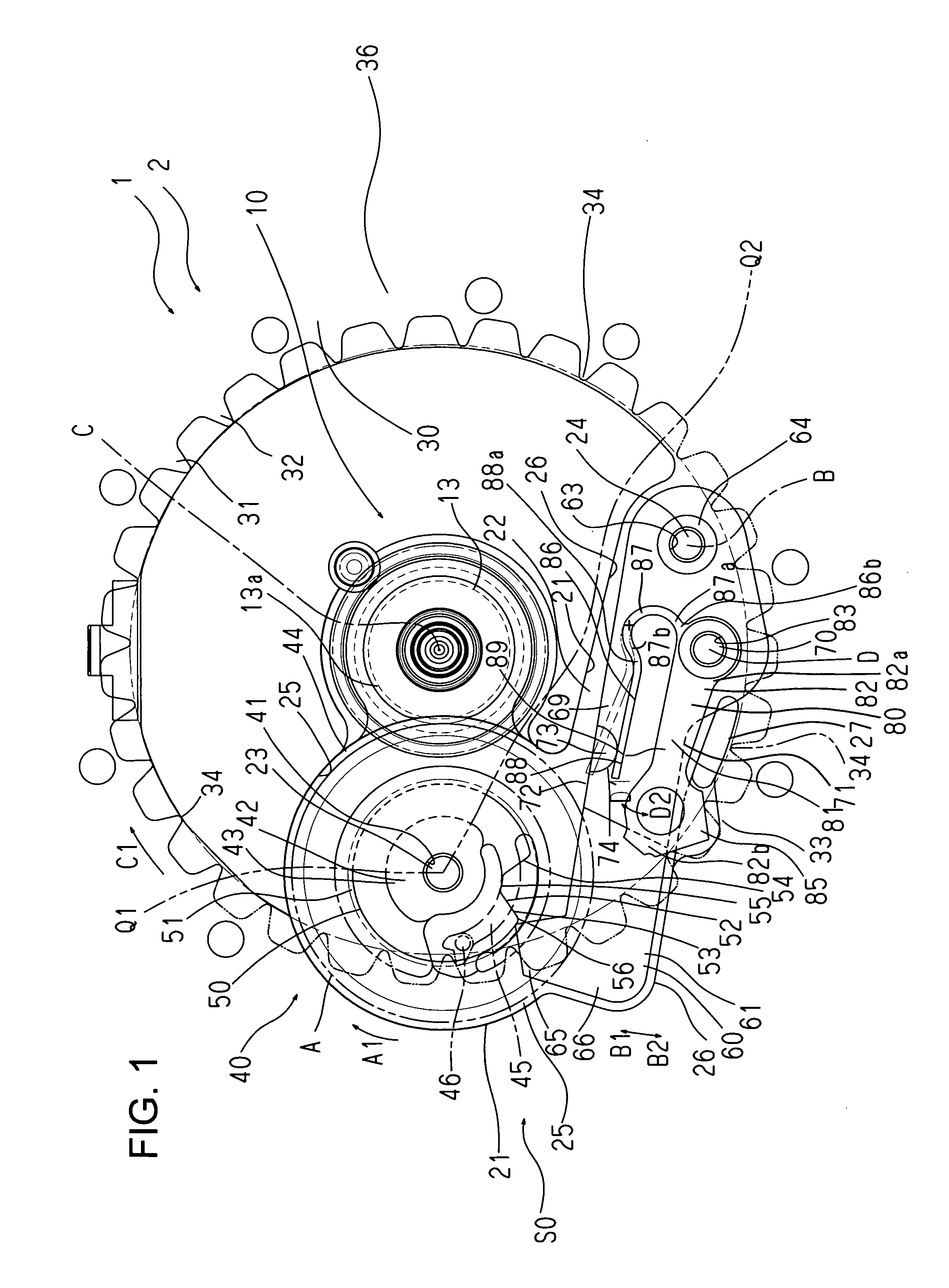
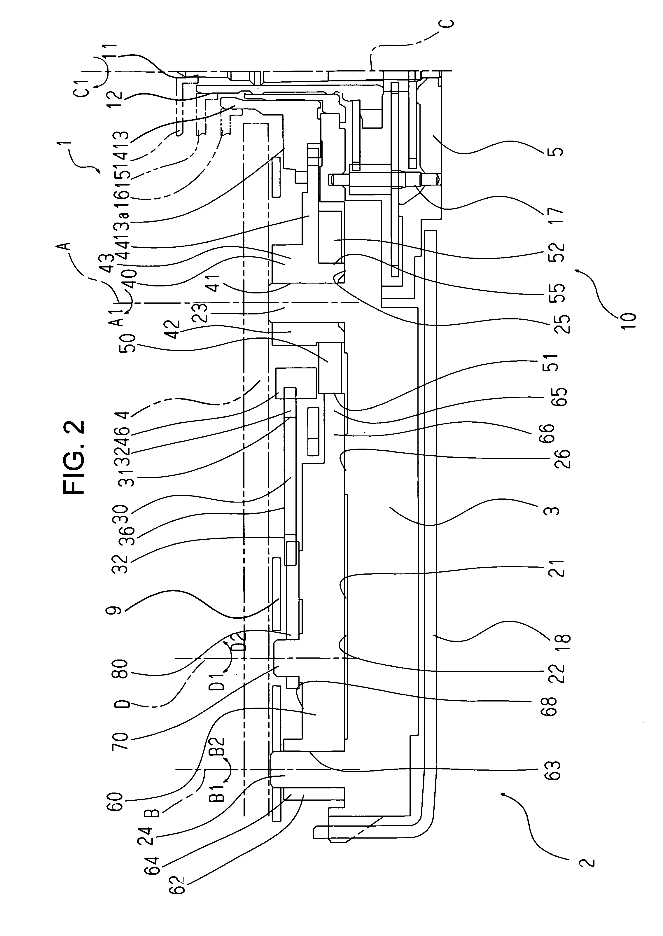
[0041]As can be seen from FIG. 1, which illustrates the outline of a calendar mechanism 1 in plan view, and FIG. 2, which shows in section a part of a timepiece 2, the timepiece 2 equipped with the calendar mechanism 1 of a preferred embodiment of the present invention is equipped with the calendar mechanism 1 on a dial 4 side of a main plate 3.

[0042]The timepiece 2 is equipped with a timepiece train wheel 10 rotatably supported by the main plate 3 and a train wheel bridge 5 and enabling time indication along a center axis C or near the center axis C. The timepiece train wheel 10 includes a second wheel & pinion 11, a center wheel & pinion 12, and an hour wheel 13 arranged coaxially around the center axis C. A second hand 14, a minute hand 15, and an hour hand 16 are attached to the distal end portions, protruding from a center hole of the dial 4, of the respective shafts or arbors of the second wheel & pinion 11, the center wheel & pinion 12, and the hour wheel 13. The second wheel...


PUM


Abstract

A calendar mechanism includes: a calendar driving wheel equipped with a calendar finger portion rotating a calendar cogwheel portion and a cam portion equipped with a torque reduction shape portion; a lever main body portion rotatably supported on a substrate, a jumper support lever equipped with a cam follower portion following the cam portion, and a jumper operating spring shoe portion provided in an intermediate portion in the longitudinal direction of the lever main body portion and formed on the same side as the cam follower portion with respect to the rotating direction thereof; and a jumper arranged so as to be rotatable with respect to the jumper support lever while overlapping the lever main body portion of the jumper support lever, the jumper being equipped with a jump control finger portion which is directed in a direction opposite to the cam follower portion of the jumper support lever and whose distal end side end portion is pressed against the calendar cogwheel portion by a jumper spring portion locked to the jumper operating spring shoe portion.

Description

BACKGROUND OF THE INVENTION[0001]1. Field of the Invention[0002]The present invention relates to a calendar mechanism and a timepiece equipped with the same.[0003]2. Description of the Related Art[0004]Well known in the art is a calendar mechanism having a date indicator equipped with a date cogwheel portion, a date indicator driving wheel equipped with a date finger portion rotating the date cogwheel portion, and a date jumper equipped with a jump control finger portion engaged with the date cogwheel portion and pressing the jump control finger portion against the date cogwheel portion and rotatably supported.[0005]In such a calendar mechanism, at the time of jump control operation of the date jumper, the degree to which the date jumper constitutes a rotational load on the date indicator is maximum when the apex portion of a tooth of the date indicator cogwheel portion is got over by the jump control finger portion (immediately before date drop). Thus, in this type of conventional ...

Claims


Application Information

Patent Timeline
Patent Type & Authority Applications(United States)
IPC IPC(8): G04B19/253
CPCG04B19/25353G04B11/008
Inventor ONO, TAMOTSU
Owner SEIKO INSTR INC
Why Eureka
Try Eureka