
Motor pretensioned roller shade

a pretensioned, roller shade technology, applied in the direction of mechanical equipment, door/window protective devices, gearing, etc., can solve the problems of low torque and motor power required to start lifting the entire weight of the shade material and the hem bar, affecting battery operated motors, and high amount of torque and power required to finish rolling up the roller shad

Active Publication Date: 2020-08-11
CRESTRON ELECTRONICS
View PDF109 Cites 8 Cited by
  • Summary
  • Abstract
  • Description
  • Claims
  • Application Information

AI Technical Summary

Benefits of technology

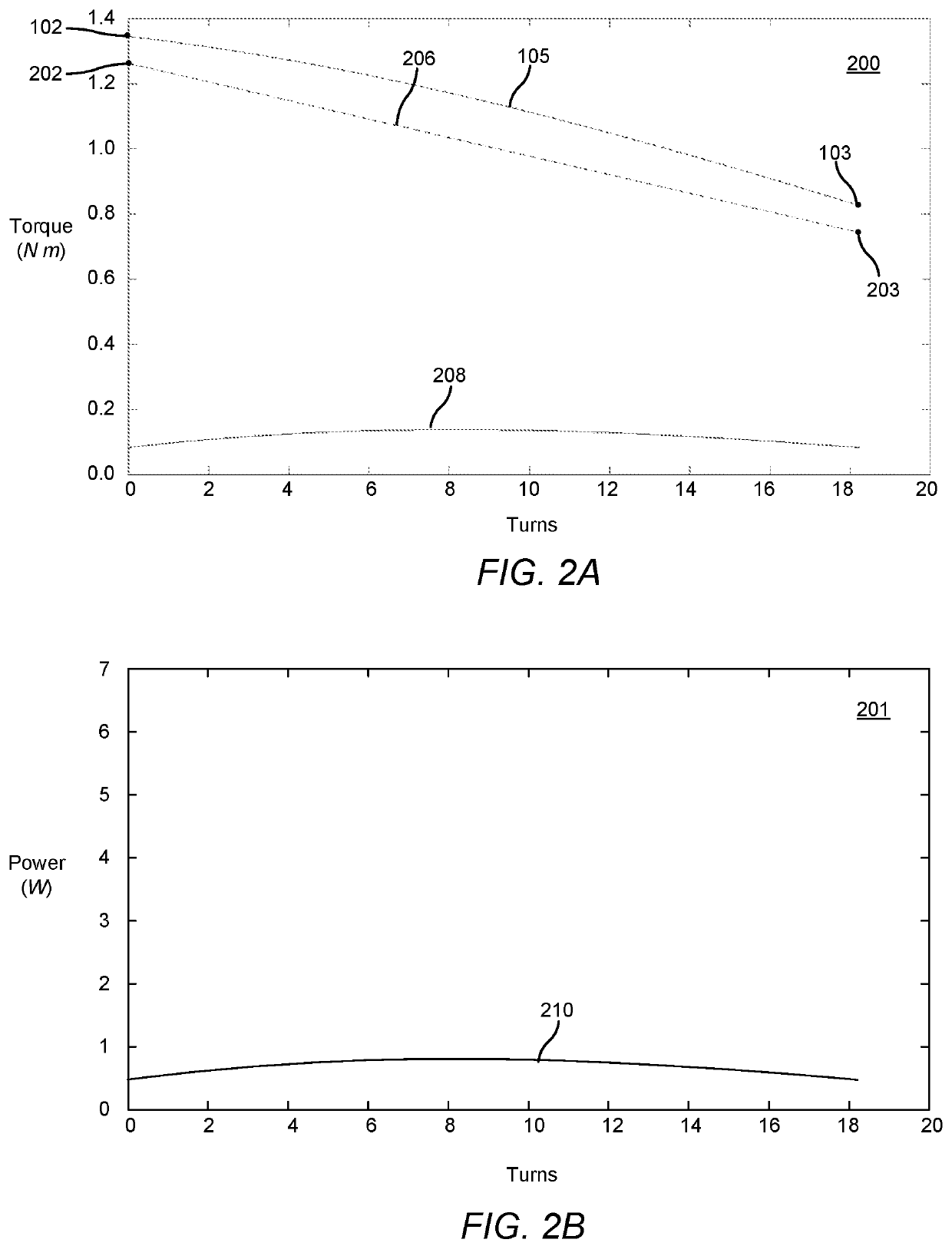
The technical effect of this patent text is to provide a system and method for counterbalancing a roller shade that reduces the torque load on the motor during the rolling up or down cycles of the shade. This is achieved by using a pretensioned spring that is controlled by a clutch mechanism that engages with the inner or outer surfaces of the spring to tighten or loosen it around a barrel, preventing or allowing further rotation of the output stage.

Problems solved by technology

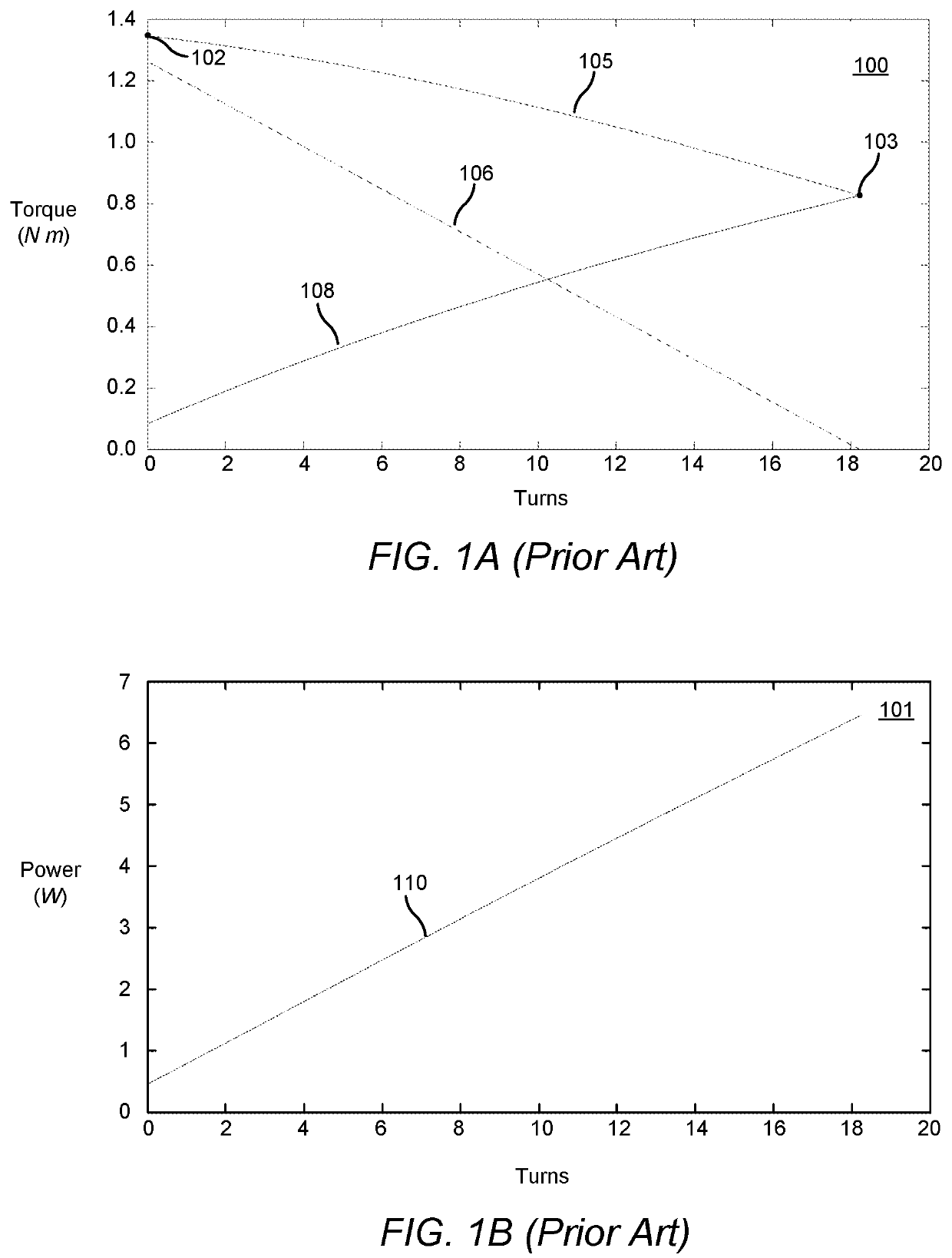
To uncover the window, however, a lot of torque and motor power are required to initially lift the entire weight of the shade material and the hem bar.
This is in particular detrimental to battery operated motors as rolling up the shade quickly drains the battery.
Thus, while the conventional torsion spring decreases the amount of torque required to roll up the roller shade in the beginning, the amount of torque and power required to finish rolling up the roller shade remains quiet high.
However, field pretensioning is often done incorrectly, leaving the customer unsatisfied with the performance of the product.
However, this preset pretension often dissipates during the continual operation of the shade, when the shade is knocked down or hit accidentally, or when the shade needs to be removed and reinstalled.
Other systems required complex field adjustment and complicated motorized pretensioning.

Method used


Image

  • Motor pretensioned roller shade
  • Motor pretensioned roller shade
  • Motor pretensioned roller shade

Examples


Embodiment Construction

[0055]The embodiments are described more fully hereinafter with reference to the accompanying drawings, in which embodiments of the inventive concept are shown. In the drawings, the size and relative sizes of layers and regions may be exaggerated for clarity. Like numbers refer to like elements throughout. The embodiments may, however, be embodied in many different forms and should not be construed as limited to the embodiments set forth herein. Rather, these embodiments are provided so that this disclosure will be thorough and complete, and will fully convey the scope of the inventive concept to those skilled in the art. The scope of the embodiments is therefore defined by the appended claims.

[0056]Reference throughout the specification to “one embodiment” or “an embodiment” means that a particular feature, structure, or characteristic described in connection with an embodiment is included in at least one embodiment of the embodiments. Thus, the appearance of the phrases “in one em...


PUM


Abstract

A roller shade is disclosed comprising a motor pretensioned counterbalancing spring that lowers the torque load on the motor of the roller shade throughout the rolling up or rolling down cycles. The roller shade comprises a motor drive unit at least partially disposed within a roller tube. The motor drive unit comprises a motor adapted to drive a drive wheel through a clutch. The motor drive unit further comprises a first spring carrier adapted to be stationary during operation of the motor drive unit. The drive wheel is operably connected to the roller tube and comprises a second spring carrier. The motor drive unit further comprises a counterbalancing spring connected at its first end to the first spring carrier and at its second end to the second spring carrier. The counterbalancing spring is pretensioned using the motor prior to inserting the motor drive unit into the roller tube by driving the drive wheel and thereby rotating the second end of the counterbalancing spring with respect to the first end of the counterbalancing spring. The clutch translates rotational motion from the motor to the drive wheel, but locks rotational motion from the drive wheel thereby locking the pretension in the counterbalancing spring.

Description

BACKGROUND OF THE INVENTIONTechnical Field[0001]Aspects of the embodiments generally relate to roller shades, and more particularly to systems, methods, and modes for a motor pretensioned roller shade.Background Art[0002]Motorized roller shades provide a convenient one-touch control solution for screening windows, doors, or the like, to achieve privacy and thermal effects. A motorized roller shade typically includes a rectangular shade material attached at one end to a cylindrical rotating tube, called a roller tube, and at an opposite end to a hem bar. The shade material is wrapped around the roller tube. An electric motor, either mounted inside the roller tube or externally coupled to the roller tube, rotates the roller tube to unravel the shade material to cover a window. To uncover the window, however, a lot of torque and motor power are required to initially lift the entire weight of the shade material and the hem bar. This is in particular detrimental to battery operated motor...

Claims


Application Information

Patent Timeline
Patent Type & Authority Patents(United States)
IPC IPC(8): E06B9/72E06B9/42F16H1/46E06B9/90E06B9/60E06B9/68
CPCE06B9/42F16H1/46E06B9/72E06B9/90E06B9/60E06B2009/725E06B2009/6809E06B2009/905
Inventor CAMPAGNA, MICHAEL
Owner CRESTRON ELECTRONICS
Learn More