Lens driving apparatus

Active Publication Date: 2011-11-24
TDK CORPARATION
View PDF8 Cites 118 Cited by
  • Summary
  • Abstract
  • Description
  • Claims
  • Application Information

AI Technical Summary

Benefits of technology

[0037]By configuring like this, there is no necessity to further establish wires to supply the driving power to the second driving portion, and the movement limitation of movable unit by wires which is for the movable unit comp

Problems solved by technology

Moreover, a conventional configuration might generate a noise due to bending or extending of th

Method used


Image

  • Lens driving apparatus
  • Lens driving apparatus
  • Lens driving apparatus

Examples


Embodiment Construction

[0047]The following explanation regarding this invention is based on the embodiments shown in Figures.

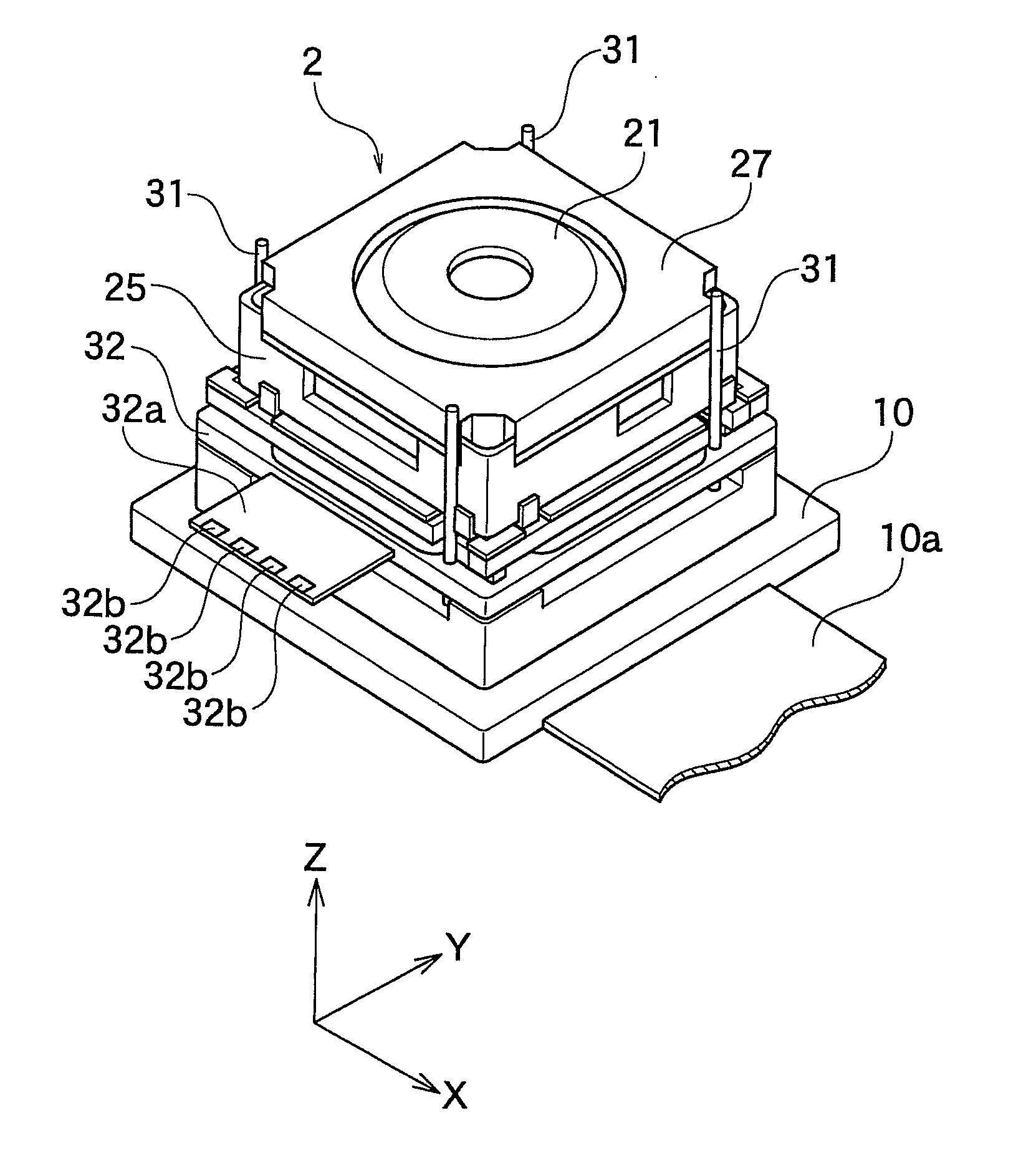
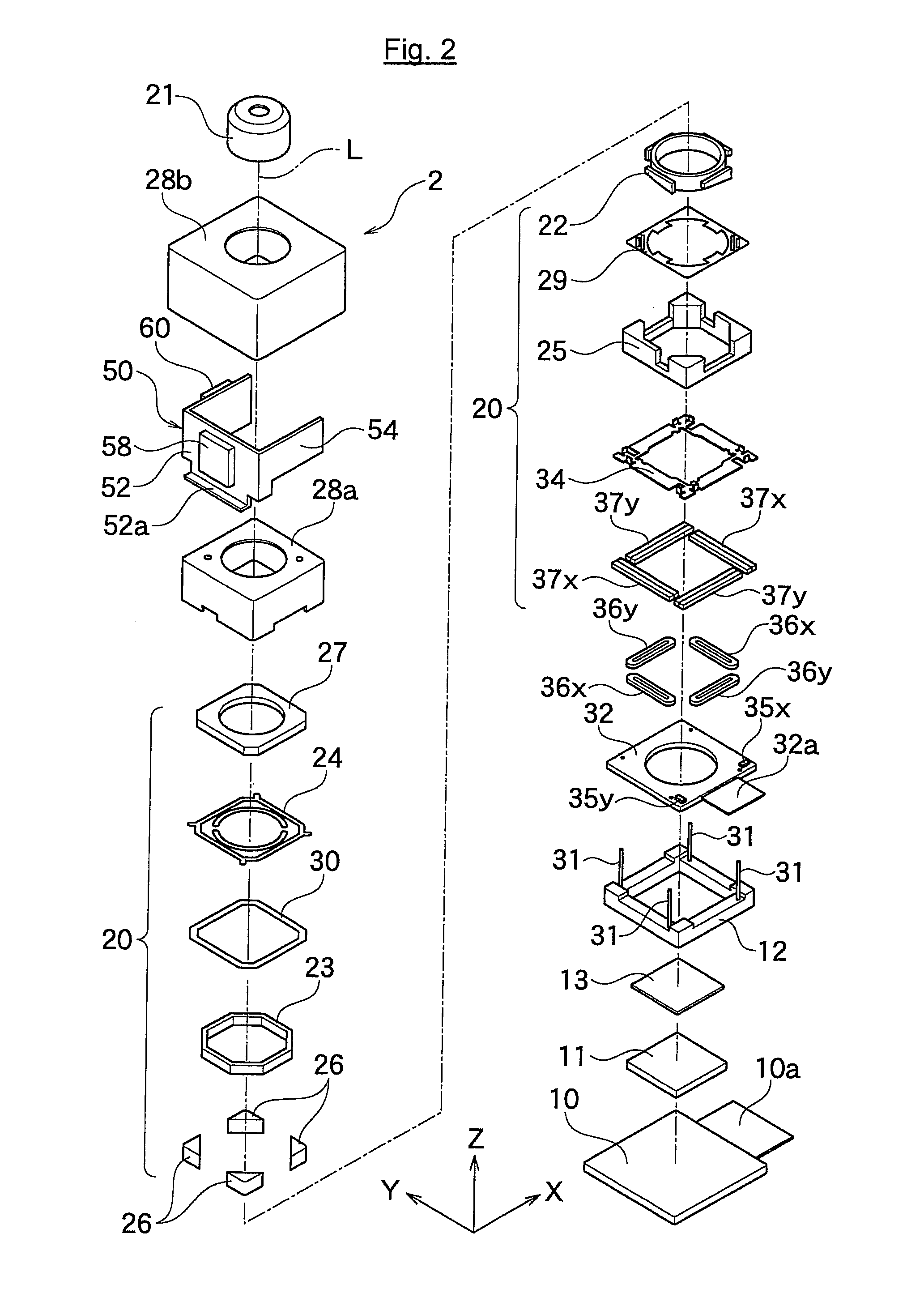
As shown in FIGS. 1 and 2, a camera unit 2 having a lens driving apparatus according to one embodiment of the present invention comprises an image sensor base plate 10 on which an image sensor 11 is fixed and a movable unit 20 supporting a lens portion 21 which guides a subject light to the image sensor 11.

[0048]Note that, in the following explanation and Figures, it will be specified that along a direction of a light axis L of the lens portion 21, a direction from the image sensor 11 to the lens portion 21 is defined as a positive direction of Z-axis, and a vertical direction to the light axis L of the lens portion 21 are defined as X-axis direction and Y axis direction. In addition, the X-axis, Y-axis and Z-axis are vertical each other. Moreover, especially in FIG. 1, a cross sectional view of a left side of the light axis L shows a cross sectional view of the X-Z axis in FIG. 2, ...


PUM


Abstract

A lens driving apparatus has a lens portion 21, a first driving portion 36 and 37 to cause a movement of a movable unit 20 including said lens portion 21 relatively to a fixed portion 10 along a vertical direction of a light axis of said lens portion 21, a second driving portion 23 and 26 to cause a movement of said lens portion relatively to said fixed portion 10 along said light axis, an image sensor 11 held on said fixed portion 10 to detect a light which comes through said lens portion 21, an inner casing 28a held on said fixed portion 10 to cover said movable unit 20 and said image sensor 11, and a planar flexible printed circuit 50 to which a shake detection sensor 58 detecting a shake of said fixed portion 10 is connected. The planar flexible printed circuit 50 is attached to contact with a sidewall surface of said inner casing 28a parallel to the light axis of said lens.

Description

BACKGROUND OF THE INVENTION[0001]1. Field of the Invention[0002]The present invention relates to a lens driving apparatus used for, for example, a camera module of mobile phone and the like.[0003]2. Description of the Related Art[0004]For a lens driving apparatus preferably used for a camera module of a mobile phone and the like, it is configured that a whole movable unit including a lens portion and an image sensor moves with respect to a fixed portion, in order to downsize the apparatus with having a mechanism of shake correction (Japanese Patent Publication No: 2009-288770).[0005]However, this conventional lens driving apparatus needs to connect a movable unit and a fixed portion by planar flexible printed circuit (FPC), in order to retrieve image data from a movable unit. Therefore, a movement of movable unit against a fixed portion for shake correction is restricted by FPC, and it needs improvement in shake correction with high accuracy.[0006]Moreover, a conventional configurat...

Claims


Application Information

Patent Timeline
IPC IPC(8): G03B17/12G03B17/00
CPCG03B3/02G03B17/12G03B17/02
Inventor HOSOKAWA, MASAHIROICHIHASHI, SHUSUKEKAWANO, NORIYUKI
Owner TDK CORPARATION
Why Eureka
Try Eureka