Rope driving device for improving control accuracy

A rope drive and control precision technology, applied in the field of robot drive control, can solve the problems of easy wear and low control precision, and achieve the effects of improving control precision, easy maintenance and easy control

Active Publication Date: 2018-11-02
NINGBO INST OF MATERIALS TECH & ENG CHINESE ACADEMY OF SCI
View PDF6 Cites 5 Cited by
  • Summary
  • Abstract
  • Description
  • Claims
  • Application Information

AI Technical Summary

Problems solved by technology

[0005] The present invention aims at the present state of the art above, and provides a rope driving device with improved control precision, which solves the shortcomings of low control precision and easy wear caused by the rope swinging along the axial direction of the reel

Method used


Image

  • Rope driving device for improving control accuracy
  • Rope driving device for improving control accuracy
  • Rope driving device for improving control accuracy

Examples


Embodiment 1

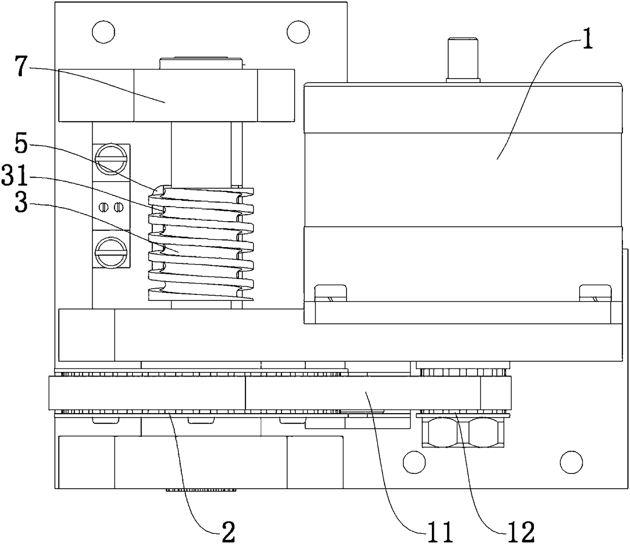
[0025] Such as Figure 1 to Figure 3 As shown, a rope driving device with improved control accuracy of the present invention includes a drive wheel 2 driven by a motor 1 , a reel 3 rotating with the drive wheel 2 , and a rope 4 wound on the reel 3 .

[0026] The motor 1, the transmission wheel and the reel 3 are respectively arranged on the mounting base, and the reel 3 can move axially relative to the transmission wheel 2 during the rotation. On the surface of the reel 3 is formed a helical groove 31 for locking the rope 4 . The axial movement rate of the reel 3 is the same as the axial movement rate of the rope 4 in the slot 31 .

[0027] The installation seat is provided with a guide member 5 for guiding the axial movement of the reel 3 . A helical guide groove 6 with the same helicity as the locking groove 31 is provided between the reel 3 and the guide member 5 , and a guide tooth 61 matched with the helical guide groove 6 is provided.

[0028] The transmission wheel 2...

Embodiment 2

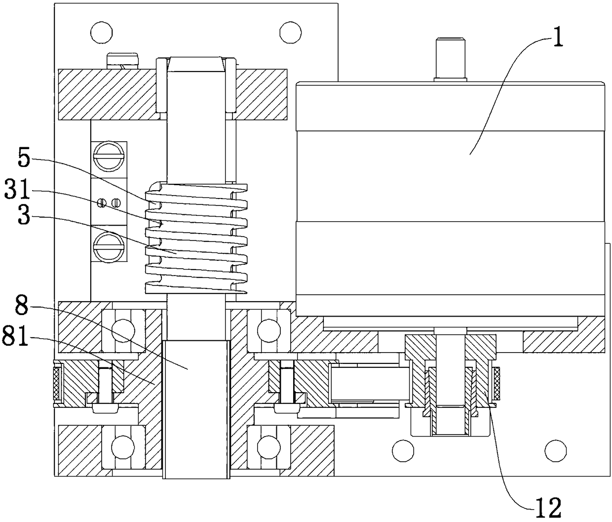
[0036] Such as Figure 4 and Figure 5 As shown, this embodiment is improved on the basis of embodiment 1. The difference from embodiment 1 is that in this embodiment, the spline shaft 8 is fixedly connected to the transmission wheel 2, and the spline shaft 8 adopts a ball spline. The spline shaft 8 is provided with a spline sleeve 81 capable of axial movement, and the reel 3 is mounted on the spline sleeve 81 .

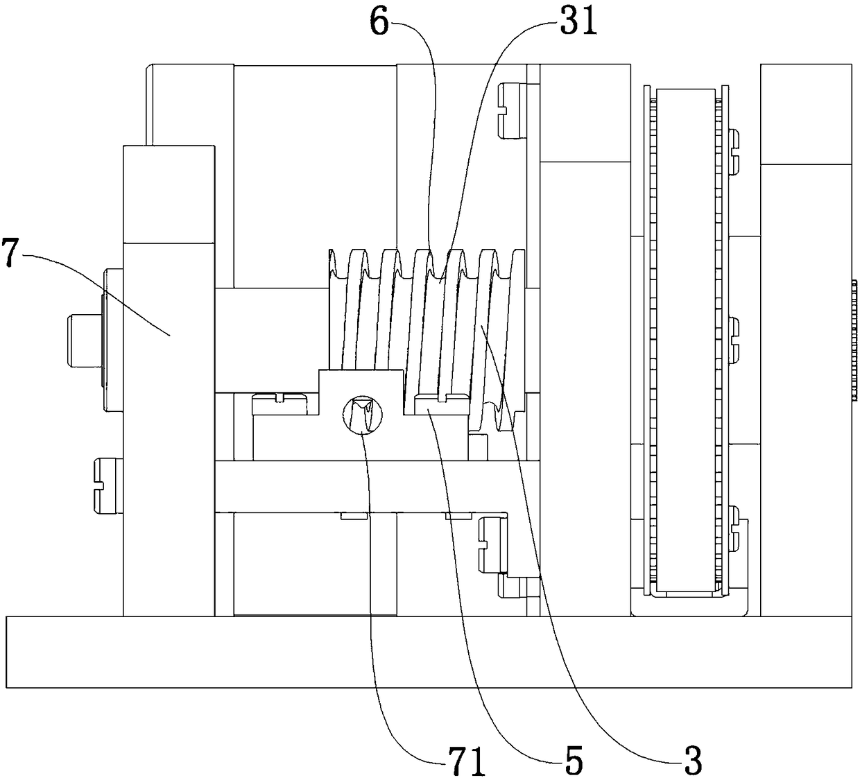
[0037] The guide piece 5 of this embodiment is fixed on the side wall of the mounting base 7 and is located on one side of the traction hole 71. The guide teeth 61 on the guide piece 5 cooperate with the helical guide groove 6 on the upper part of the helical groove.

Embodiment 3

[0039] Such as Figure 6 to Figure 8 As shown, the rope driving device of this embodiment also includes a transmission wheel 2 driven by a motor 1 , a reel 3 rotating with the transmission wheel 2 , and a rope 4 wound on the reel 3 .

[0040] The motor 1, the transmission wheel and the reel 3 are respectively arranged on the mounting base, and the reel 3 can move axially relative to the transmission wheel 2 during the rotation. On the surface of the reel 3 is formed a helical groove 31 for locking the rope 4 . The axial movement rate of the reel 3 is the same as the axial movement rate of the rope 4 in the slot 31 .

[0041]The installation seat is provided with a guide member 5 for guiding the axial movement of the reel 3 . A helical guide groove 6 with the same helicity as the locking groove 31 is provided between the reel 3 and the guide member 5 , and a guide tooth 61 matched with the helical guide groove 6 is provided.

[0042] The transmission wheel 2 is rotatably arr...


PUM


Abstract

The invention discloses a rope driving device for improving the control accuracy. The rope driving device comprises a transmission wheel driven to rotate by a motor, a reel rotating along with the transmission wheel, and a rope wound on the reel; the reel can move relative to the transmission axle in the rotating process, and a spiral clamping groove used for clamping the winding of the rope is formed in the surface of the reel; and the axial movement rate of the reel is the same as that of the rope in the clamping groove, through the synchronous movement of the separation point of the reel and the rope, the swing of the rope relative to the reel is eliminated, and the output of the rope can be accurately controlled accordingly. The rope driving device has the key advantages that the rotating angle of the reel is linearly related to the input and output amount of the rope, the rope driving device is easy to control, compact in structure and easy to maintain, and the control accuracy ofthe rope is greatly improved.

Description

technical field [0001] The invention relates to robot driving control technology, in particular to a rope driving device for a rope-driven robot. Background technique [0002] The rope-driven robot is a special hybrid mechanism that drives the movement of the motion platform by ropes, and consists of several single-degree-of-freedom or multi-degree-of-freedom rope-driven joints. Rope-driven robots have the advantages of light weight, small inertia, strong load-bearing capacity, and good flexibility, so they are very suitable for application in service robots and have high research value. [0003] The rope-driven device is one of the most important components of the rope-driven manipulator, and the movement of the rope-driven joint is realized by pulling the rope. The performance and precision of the rope-driven device directly determine the performance and precision of the entire rope-driven manipulator. Since the rope-actuated robot is a drive redundant mechanism, the num...

Claims


Application Information

Patent Timeline
Patent Type & Authority Applications(China)
IPC IPC(8): B25J9/10
CPCB25J9/1045
Inventor 杨桂林王逸杨凯盛王慰军郑天江张驰
Owner NINGBO INST OF MATERIALS TECH & ENG CHINESE ACADEMY OF SCI
Why Eureka
Try Eureka