Device and method for grinding workpieces using a control unit

a control unit and workpiece technology, applied in the direction of grinding machine components, grinding/polishing apparatus, grinding machines, etc., can solve the problems of solid workpieces, inflexible workpieces, and inability to process, and achieve the effect of easy calculation

Active Publication Date: 2015-08-27
MATUSCHEK MESSTECHN
View PDF7 Cites 6 Cited by
  • Summary
  • Abstract
  • Description
  • Claims
  • Application Information

AI Technical Summary

Benefits of technology

[0031]In practice, each of the fastening elements can be displaceable parallel to the initial direction by the actuating rod fastened therein using the actuator, when the bearing plane extends parallel to the initial plane. The initial direction can in practice extend parallel to the guide rod. In other words, each actuator shifts the fastening element assigned thereto parallel to the initial direction when the plane of the swash plate is oriented parallel to the initial plane. These geometrical preconditions result in relatively easy calculations for changing the position of the swash plate in dependence on the particular actuation of the actuators. The geometrical relationships and the kinematics of the drive elements

Problems solved by technology

However, such a procedure is impossible in the case of solid, non-flexible workpieces, since the latter are not bent by the grinding force.
The surfaces of the welding electrodes can be impaired by deposits an

Method used


Image

  • Device and method for grinding workpieces using a control unit
  • Device and method for grinding workpieces using a control unit
  • Device and method for grinding workpieces using a control unit

Examples


Embodiment Construction

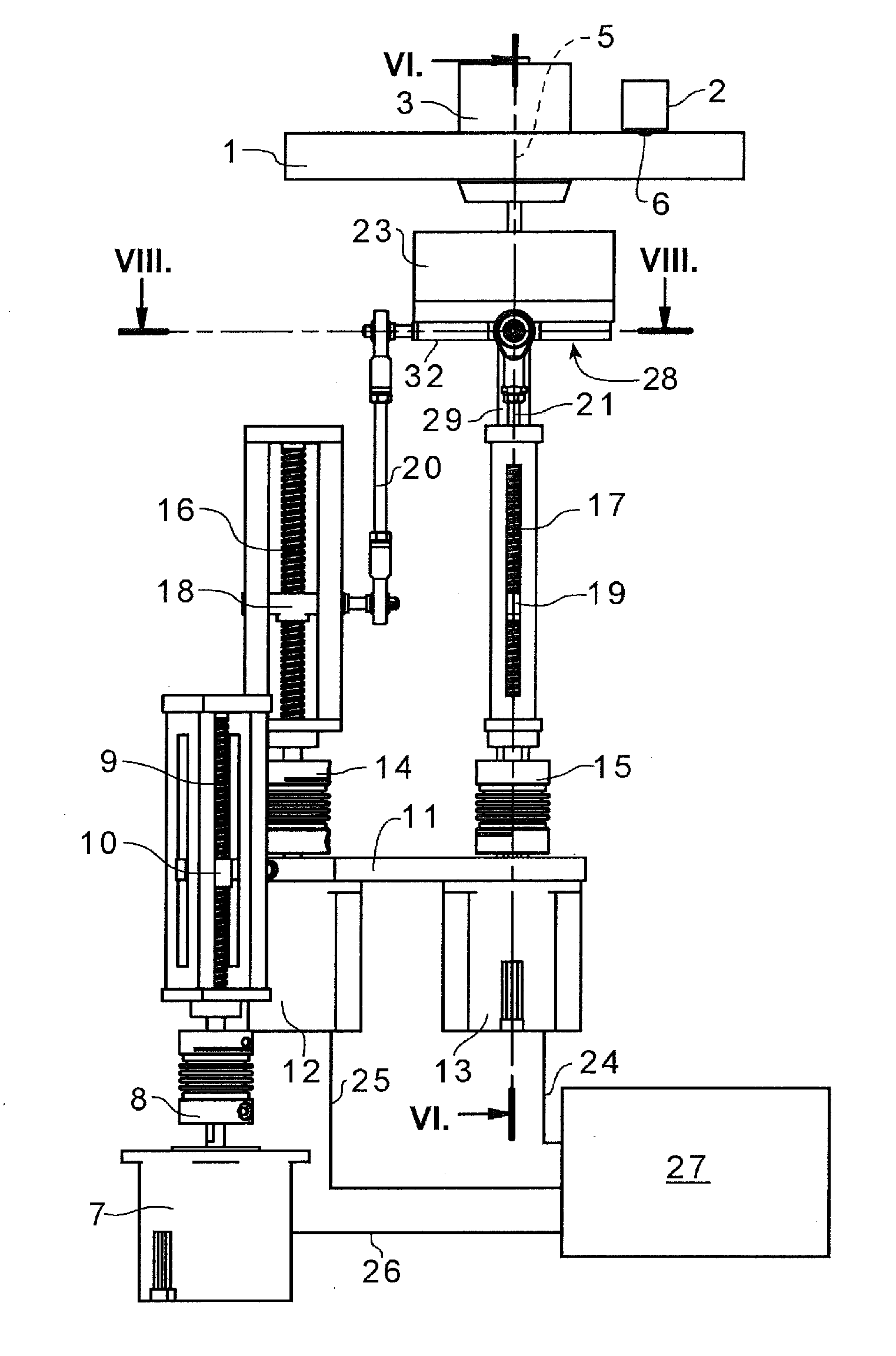
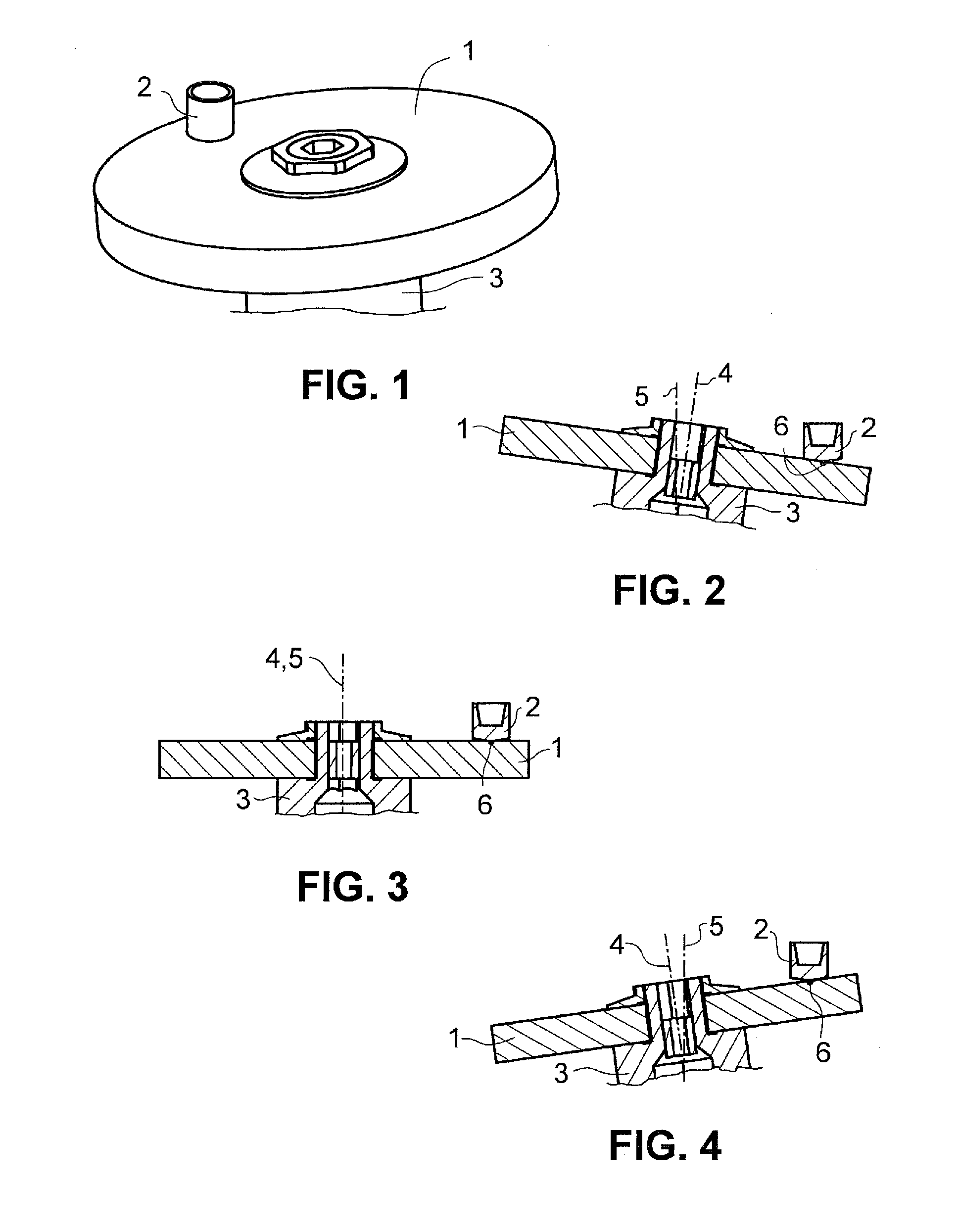
[0045]FIGS. 1 to 4 illustrate the grinding that is desired with the grinding device described here. The grinding wheel 1 and the workpiece 2 are depicted here. The grinding wheel 1 is configured in a flat manner, i.e. it has two mutually parallel grinding surfaces. In the illustration shown, the workpiece 2 is a copper welding electrode. The welding electrode 2 is drawn in an exposed manner. In practice, it is moved to the grinding wheel 1 by welding tongs fastened to a robot arm. The grinding wheel 1 may include an elastic, optionally foamed plastics material, to the disk-like top side and underside of which abrasives have been applied. However, rigid grinding wheels 1 are also used. The grinding wheel 1 is fixedly screwed to a hub 3 which is pivotable and displaceable in the present grinding device.

[0046]The axis of rotation of the bearing of the grinding wheel is provided with the reference number 4 in FIGS. 2 to 4. The bearing itself is not illustrated.

[0047]The vertical directi...


PUM

PropertyMeasurementUnit
Distanceaaaaaaaaaa

Abstract

A system for grinding solid workpieces includes a grinding wheel, a bearing for rotatable mounting of the grinding wheel about an axis of rotation, and a grinding wheel drive for rotating the grinding wheel. The system allows the production of freely-definable surfaces on the face of the rigid workpiece that comes into contact with the grinding wheel. The bearing is fastened to a pivotable and displaceable bearing carrier. The bearing plane is pivotable in any desired direction with respect to an initial plane and is displaceable in a direction perpendicular to the initial plane. Actuators are coupled to the bearing carrier to pivot and displace the bearing carrier. A digital control unit controls and synchronizes the actuators such that the surface of the grinding wheel creates a freely-definable face about a positionally fixed reference point which is at a radial distance from the center point of the grinding wheel.

Description

TECHNICAL FIELD[0001]This application relates to the field of grinding solid workpieces.BACKGROUND OF THE INVENTION[0002]In order to grind the ends of flexible bristles of brushes, the document DE 297 13 087 U1, which is incorporated herein by reference, discloses a device in which a conical grinding wheel rotates about an axis of rotation and at the same time is rotatable in a manner revolving about a second axis extending obliquely with respect to the axis of rotation. The angle of slant of the second axis corresponds to the angle of taper of the grinding wheel, and the flexible bristles are pressed against the grinding wheel substantially at the intersecting point of the second axis with the surface of the grinding wheel. This results substantially in a horizontally extending surface of the grinding wheel in contact with the bristles because of the angle of slant and angle of taper being identical in value when the second axis extends vertically. Using the revolving turning of th...

Claims


Application Information

Patent Timeline
IPC IPC(8): B24B41/04B24B45/00
CPCB24B45/00B24B41/04
Inventor PIEREDNIK, CHRISTOPHLANGE, ELMARWEINHARDT, JOERG
Owner MATUSCHEK MESSTECHN
Why Eureka
Try Eureka