Thrust constant derivation method and movement control method of linear motor, and thrust constant derivation device and movement control device of linear motor

a technology of thrust constant and derivation method, which is applied in the field of linear motors, can solve the problems of increasing costs and decreasing tolerances

Active Publication Date: 2016-10-27
FUJI MASCH MFG CO LTD
View PDF7 Cites 6 Cited by
  • Summary
  • Abstract
  • Description
  • Claims
  • Application Information

AI Technical Summary

Benefits of technology

[0020]Accordingly, it is possible to carry out movement control method of the linear motor according to the present disclosure, and the same effects occur with the disclosed device.

Problems solved by technology

However, decreasing tolerances of the management links directly to the demerit of an increase in costs.

Method used


Image

  • Thrust constant derivation method and movement control method of linear motor, and thrust constant derivation device and movement control device of linear motor
  • Thrust constant derivation method and movement control method of linear motor, and thrust constant derivation device and movement control device of linear motor
  • Thrust constant derivation method and movement control method of linear motor, and thrust constant derivation device and movement control device of linear motor

Examples


Embodiment Construction

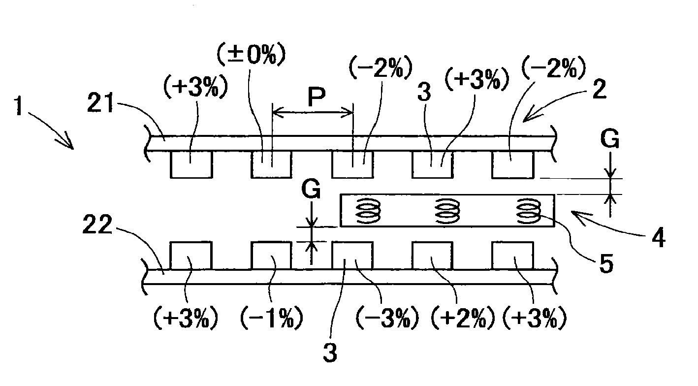
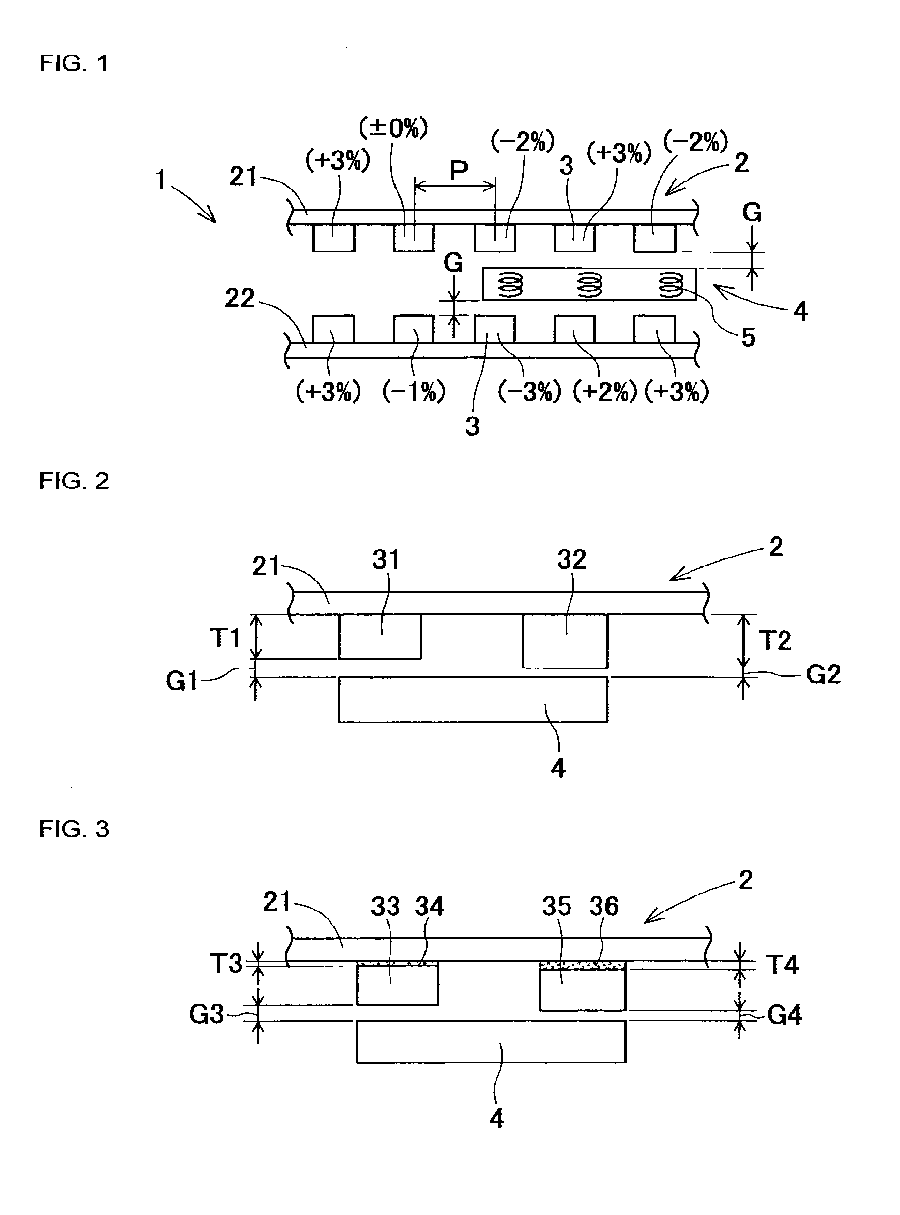
[0039]Description will be given of a thrust constant derivation method of a linear motor of the first embodiment of the present disclosure, with reference to FIGS. 1 to 17. First, description will be given of a basic configuration example of a linear motor 1 which is used in the first embodiment. FIG. 1 is a plan diagram illustrating a basic configuration example of the linear motor 1. The linear motor 1 is formed of a track member 2 and a moving body 4.

[0040]The track member 2 includes two long rails 21 and 22 which are arranged in parallel. The long rails 21 and 22 extend in the left-right direction of FIG. 2 which is the movement direction of the moving body 4. A plurality of permanent magnets 3 are provided to line up in the movement direction at a substantially fixed installation pitch P on the surfaces of the long rails 21 and 22 which face each other. FIG. 1 illustrates 10 of the permanent magnets 3, and a further multitude of the permanent magnets 3, which are omitted from t...


PUM


Abstract

A method of deriving a thrust constant representing an occurrence rate of a thrust in relation to a current in a linear motor which includes a magnet extending in a movement direction, and a moving body which includes a coil mounted to a track member in a movable manner, the linear motor generating a thrust in the movement direction between the magnet and the coil by causing the current to flow in the coil, in which an average thrust constant which is an average thrust constant in a long movement zone on the track member is derived based on actual measurement, local thrust constants which are local thrust constants of a plurality of locations on the track member are derived based on each actual measurement, and the thrust constants are derived based on the average thrust constant and the local thrust constant of each location.

Description

TECHNICAL FIELD[0001]The present disclosure relates to a linear motor in which a moving body moves along a track member due to a thrust which is generated between a coil with a current running therethrough and a magnet. More specifically, the present disclosure relates to a method and a device which derive a thrust constant which changes depending on the position of the moving body, and to a method and a device which control the movement of the moving body using the derived thrust constant.BACKGROUND ART[0002]A solder printer, a component mounting machine, a reflow furnace, a board inspection machine, and the like are examples of equipment which manufacture a printed circuit board onto which multiple electronic components are mounted. Such equipment is generally connected by board conveyance devices to construct a board production line. In the component mounting machine or the board inspection machine, a feeding screw drive device has been used from the related art as a drive device...

Claims


Application Information

Patent Timeline
Patent Type & Authority Applications(United States)
IPC IPC(8): H02P25/064H02P6/00
CPCH02P25/064H02P2205/05H02P6/006H02P25/06H02K41/031H02P25/062
Inventor KAWASHIMA, HIROKINAGATA, RYO
Owner FUJI MASCH MFG CO LTD
Why Eureka
Try Eureka