
Fixing device, image forming apparatus, and heat generation belt

Inactive Publication Date: 2011-11-24
KONICA MINOLTA BUSINESS TECH INC
View PDF3 Cites 20 Cited by
  • Summary
  • Abstract
  • Description
  • Claims
  • Application Information

AI Technical Summary

Benefits of technology

[0015]In view of the aforementioned problems, the present invention aims to provide a heat generation belt having a heat-generation characteristic which has a high degree of energy efficiency and which is manufactured applying a simple manufacturing method, a fixing device including the heat generation belt, and an image forming apparatus including the same.
[0016]One aspect of the present invention is a fixing device for fixing an unfixed image onto a recording sheet by applying heat and pressure to the unfixed image while the recording sheet having the unfixed image formed thereo

Problems solved by technology

As a result, there are cases where the amount of heat generated at the end portions of the heat generation belt does not reach a desired level required for heat fixing.
Such problem gives rise to a demand for a heat generation belt which generates a greater amount of heat at the end portions thereof compared to the center portion.
Such problem gives rise to a demand for a heat generation belt which generates a greater amount of heat at a center portion thereof compared to the end portions thereof.
However, the methods of cooling predetermined portions of the heat generation belt by using a fan and providing portions of the heat generation belt with different heat radiation characteristics are unsatisfactory in terms of energy efficiency.

Method used


Image

  • Fixing device, image forming apparatus, and heat generation belt
  • Fixing device, image forming apparatus, and heat generation belt
  • Fixing device, image forming apparatus, and heat generation belt

Examples


embodiment 1

1. Embodiment 1

[0031]Below, description is made focusing on a heat generation belt having a heat generation characteristic in which both end portions of the heat generation belt generate a greater amount of heat compared to a center portion thereof, as one embodiment of the present invention.

(1) Structure of an Image Forming Apparatus 10

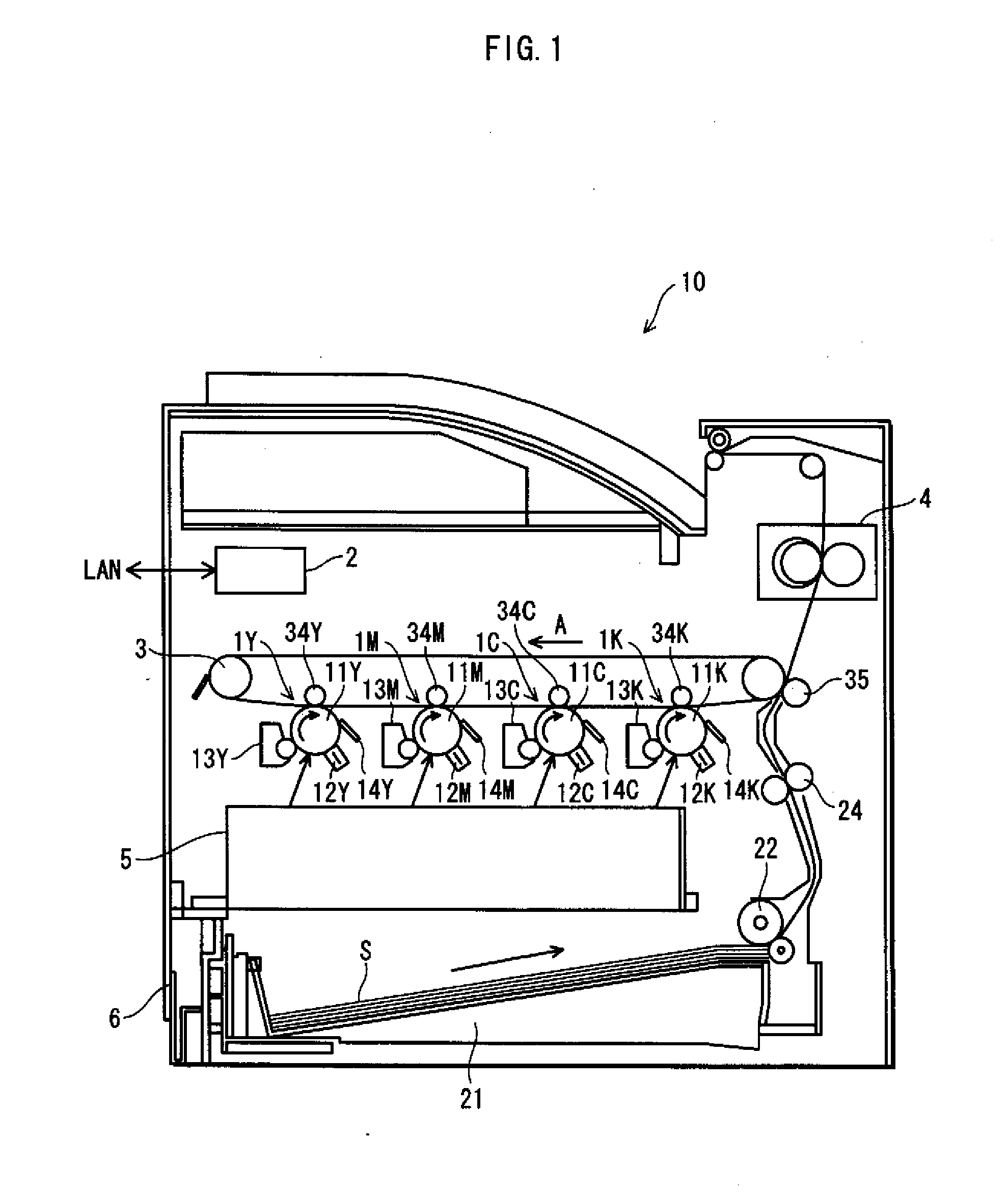
[0032]FIG. 1 shows an overall structure of an image forming apparatus 10 pertaining to the present invention.

[0033]As illustrated in FIG. 1, the image forming apparatus 10 includes: a plurality of processing units which are labeled 1Y, 1M, 1C, and 1K; a control unit 2; an intermediate transfer belt 3; a fixing device 4; an optical unit 5; and a sheet feeder 6, all of which are housed inside a main body thereof. The image forming apparatus 10 is a full-color, multifunction printer which is provided with the functions of a scanner, a printer, a FAX, and etc.

[0034]In the following, description is made on each of the components of the image forming appar...

embodiment 2

2. Embodiment 2

[0099]In the following, description is made focusing on a heat generation belt having a heat generation characteristic in which a center portion thereof in the rotational axis direction generates a greater amount of heat compared to both end portions thereof, as another embodiment of the present invention.

(1) Structure

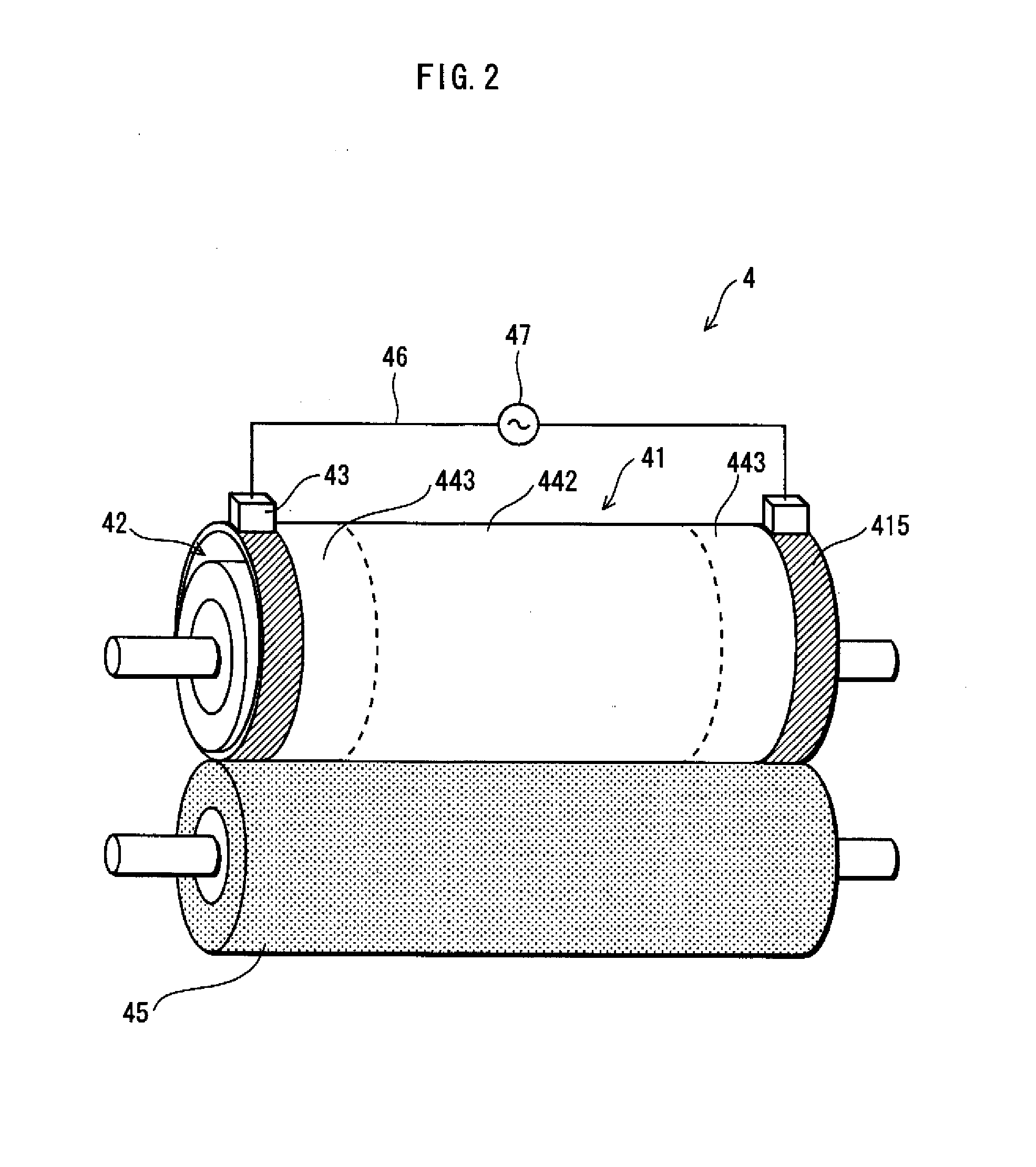
[0100]An image forming apparatus and a fixing device pertaining to embodiment 2 of the present invention has a similar structure as the image forming apparatus 10 and the fixing device 4 illustrated in FIGS. 1 and 2.

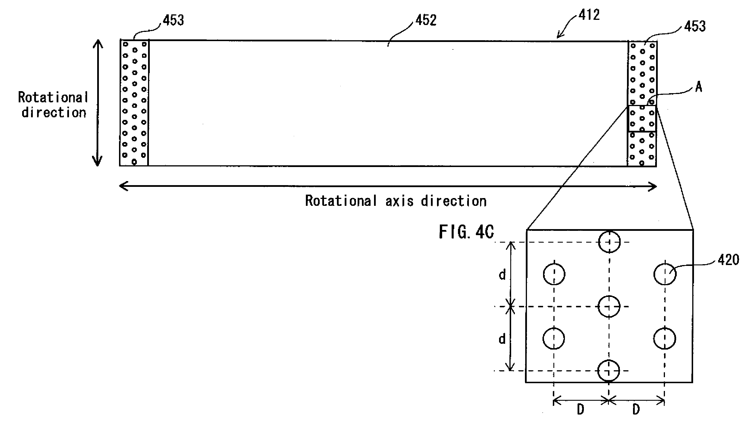
[0101]In addition, a heat generation fixing belt 41 pertaining to embodiment 2 includes a plurality of through-holes 420 penetrating the resistive heat generation layer 412 (refer to FIG. 3), which is similar to embodiment 1. However, embodiment 2 differs from embodiment 1 in that the through-holes 420 are provided so that the amount of heat generated at the center portion of the heat generation fixing belt 41 is greater compared to the amoun...


PUM


Abstract

The present invention provides a fixing device for fixing an unfixed image onto a recording sheet by applying heat and pressure to the unfixed image while the recording sheet having the unfixed image formed thereon is passing through a fixing nip, the fixing nip being formed by pressing a pressurizing roller against a heat generation belt, wherein the heat generation belt rotates around a rotational axis and includes a resistive heat layer extending in a rotational axis direction thereof, the resistive heat layer configured to generate heat when electricity is supplied thereto and having a plurality of holes provided therein, and the holes are distributed unevenly in the resistive heat layer such that electrical resistivity of the resistive heat layer varies in the rotational axis direction.

Description

[0001]This application is based on an application No. 2010-118023 filed in Japan, the contents of which are hereby incorporated by reference.BACKGROUND OF THE INVENTION[0002](1) Field of the Invention[0003]The present invention relates to a fixing device incorporated in an image forming apparatus and a heat generation belt which is one of the main components thereof, and in particular to a technology for varying the amount of heat generated along a heat generation belt that includes a resistive heat generation layer.[0004](2) Description of the Related Art[0005]Proposals have been made of structures of a fixing belt for a fixing device. According to the proposals, a resistive heat generation layer and an electrode layer are provided on an insulation belt to form the fixing belt. In such fixing belts, electricity is directly provided to the resistive heat generation layer via the electrode layer, and the heat generation layer generates heat by so-called Joule heating. Accordingly, he...

Claims


Application Information

Patent Timeline
IPC IPC(8): G03G15/20
CPCG03G15/2042
Inventor ISHIHARA, YASUHIROWATANABE, ISAOTANAKA, TOSHIAKISASAKI, KOSUKE
Owner KONICA MINOLTA BUSINESS TECH INC
Learn More