Blood pressure monitor

a blood pressure monitor and monitor technology, applied in the field of medical devices, can solve the problems of complicated ptt-based blood pressure measurement, short ptt, and inability to accurately measure blood pressure, and achieve the effect of convenient and quick blood pressure measuremen

Inactive Publication Date: 2011-11-24
SOTERA WIRELESS
View PDF5 Cites 41 Cited by
  • Summary
  • Abstract
  • Description
  • Claims
  • Application Information

AI Technical Summary

Benefits of technology

[0012]To address any deficiencies in the prior art, the present invention provides blood pressure monitor featuring a substrate that includes small-scale optical, electrical, and acoustic sensors. The substrate, for example, may be a single, continuous component, or alternatively may consist of a first component (e.g. a disposable adhesive material) that connects or attaches to a second component (e.g. a non-disposable insert that comprises the sensors). The sensors measure, respectively, time-dependent optical, electrical and acoustic waveforms that a processor then analyzes as described in detail below to determine blood pressure. In this way, the substrate replaces a conventional cuff to make a rapid, comfortable measurement of blood pressure.
[0013]The substrate can be integrated into a number of product configurations. For example, it can be attached to an adhesive backing and used as a stand-alone patch. In this configuration, a cable with a detachable connector typically connects to a tab connector fabricated directly onto the substrate. The other end of the cable connects to a hand-held console. This way, the patch can be adhered to a patient for an extended period of time to make quasi-continuous measurements, or can simply be connected to the console to make sporadic, one-time measurements. In another embodiment, the optical, electrical, and acoustic sensors are included in a circuit board attached to the end of the cable. In this case the circuit board can “snap” into a disposable adhesive sensor, which in turn attaches to the patient. By including the relatively expensive electrical components in the cable, this embodiment minimizes the cost of the disposable component, which is comprised mostly of an adhesive pad and solid, conductive gel associated with the electrodes.

Problems solved by technology

Typically a high blood pressure results in a shorter PTT.
PTT-based measurements of blood pressure are complicated by a number of factors, one of which is the many time-dependent processes associated with each heartbeat that may correlate in a different way with blood pressure, or in fact may not correlate at all.
This causes the ventricle to fill with blood and increase in pressure.

Method used


Image

  • Blood pressure monitor
  • Blood pressure monitor
  • Blood pressure monitor

Examples


Embodiment Construction

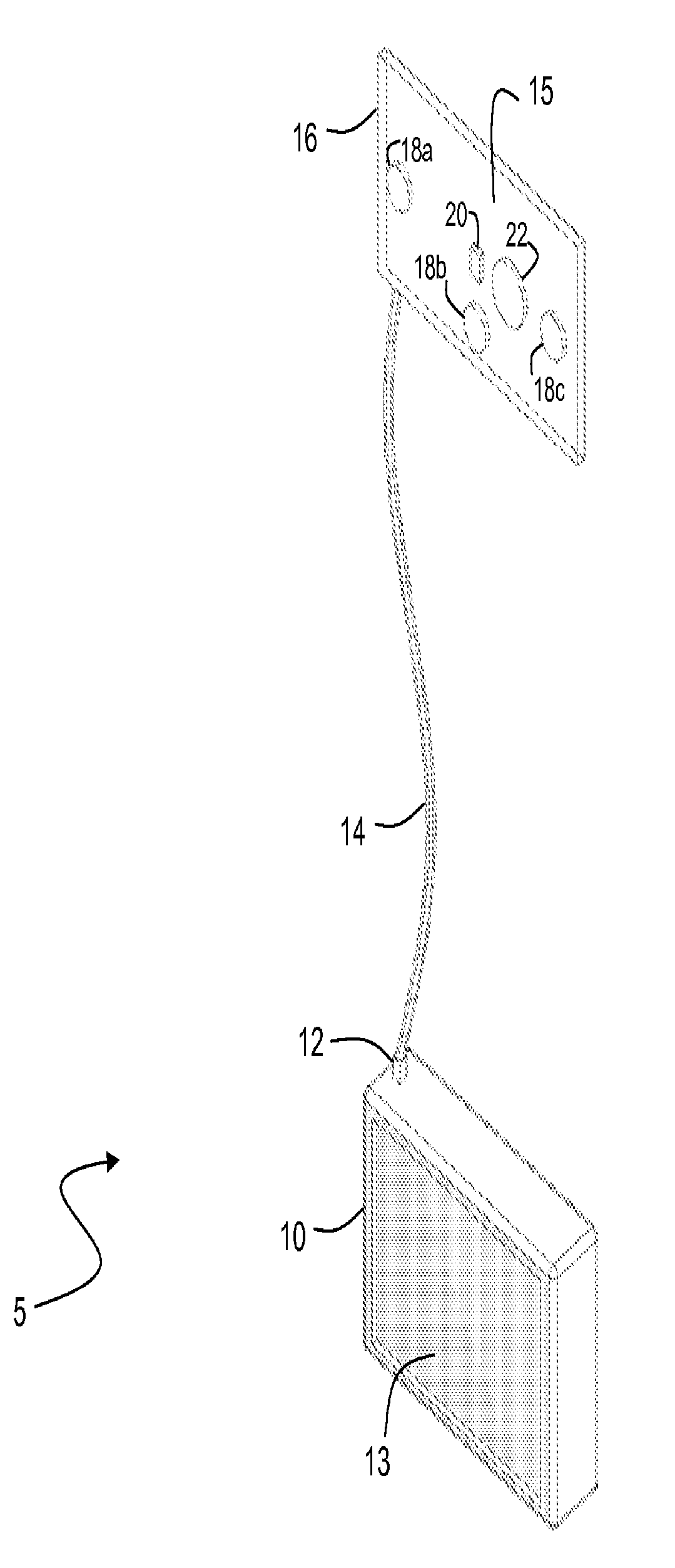
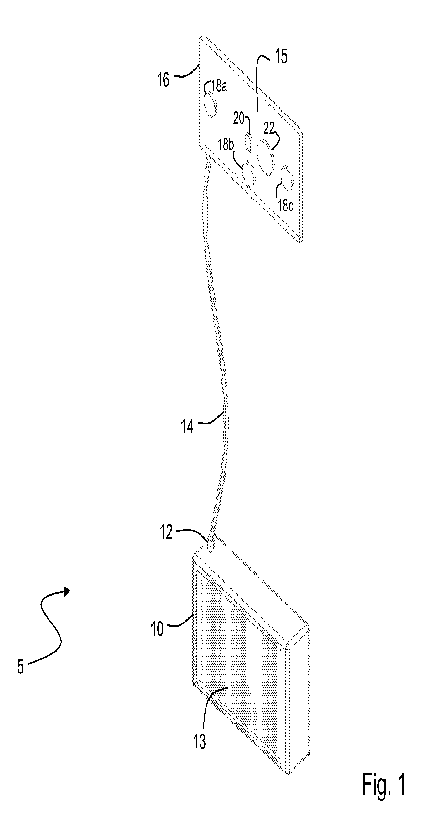
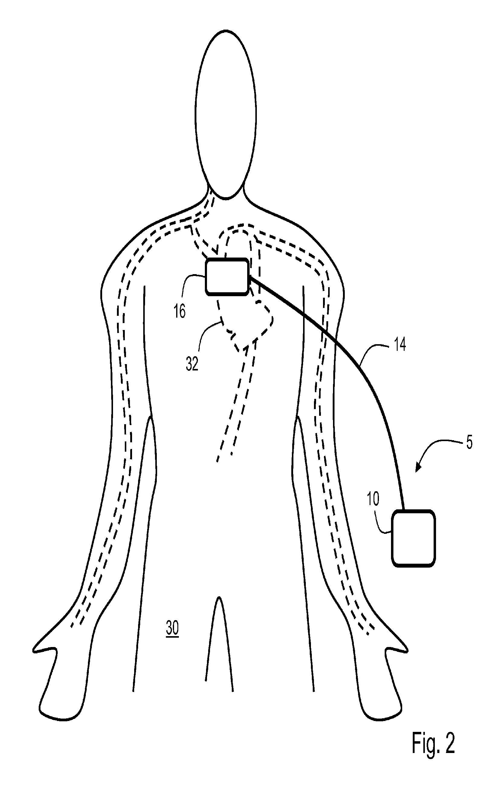
[0036]FIG. 1 shows a preferred embodiment of a blood pressure monitor 5 according to the invention that includes a console 10 that attaches to a flexible foam pad 16 through a cable 14. The flexible foam pad 16 includes a substrate 15 that supports sensors that measure time-dependent electrical, optical, and acoustic waveforms (shown in FIGS. 3A, 3B). The substrate 15 is preferably a flexible printed circuit board that adheres to the foam pad 16. During operation, the flexible foam pad 16 preferably contacts an area below a patient's sternal notch to measure the various waveforms from a patient. A microprocessor in the console 10 analyzes the waveforms to determine the systolic time intervals, which are then processed with an algorithm and a weighted average to determine the patient's real-time blood pressure.

[0037]The flexible foam pad 16 preferably includes three electrodes 18a-c that measure two electrical signals and a ground (or other) signal from the patient. Two of the electr...


PUM


Abstract

The invention provides a method for measuring a blood pressure value of a user featuring the following steps: 1) generating optical, electrical, and acoustic waveforms with, respectively, optical, electrical, and acoustic sensors attached to a single substrate that contacts a user; 2) determining at least one parameter by analyzing the optical and acoustic waveforms; and 3) processing the parameter to determine the blood pressure value for the user.

Description

CROSS REFERENCES TO RELATED APPLICATION[0001]This application is a continuation of co-pending U.S. patent application Ser. No. 11 / 530,076, filed Sep. 8, 2006, and incorporated herein by reference.STATEMENT REGARDING FEDERALLY SPONSORED RESEARCH OR DEVELOPMENT[0002]Not ApplicableBACKGROUND OF THE INVENTION[0003]1. Field of the Invention[0004]The present invention relates to medical devices for monitoring vital signs such as blood pressure.[0005]2. Description of the Related Art[0006]Pulse transit time (“PTT”), defined as the transit time for a pressure pulse launched by a heartbeat in a patient's arterial system, has been shown in a number of studies to correlate to both systolic and diastolic blood pressure. In these studies PTT is typically measured with a conventional vital signs monitor that includes separate modules to determine both an electrocardiogram (ECG) and pulse oximetry. During a conventional PTT measurement, multiple electrodes typically attach to a patient's chest to ...

Claims


Application Information

Patent Timeline
Patent Type & Authority Applications(United States)
IPC IPC(8): A61B5/021
CPCA61B5/0059A61B5/02028A61B5/021A61B5/7239A61B5/0402A61B5/6833A61B7/04A61B5/026A61B5/02125A61B5/318
Inventor BANET, MATTHEW JOHNTHOMPSON, MICHAEL JAMESZHOU, ZHOU
Owner SOTERA WIRELESS
Why Eureka
Try Eureka