Stereo acoustic signal encoding apparatus, stereo acoustic signal decoding apparatus, and methods for the same

a stereo acoustic signal and encoding technology, applied in the field of stereo acoustic signal encoding apparatus, stereo acoustic signal decoding apparatus, and methods, can solve the problems of deterioration of the quality of a signal, unstable stereo feeling, unstable stereo feeling in some tests, etc., to reduce the amount of computational complexity

Active Publication Date: 2011-11-24
III HLDG 12 LLC
View PDF13 Cites 53 Cited by
  • Summary
  • Abstract
  • Description
  • Claims
  • Application Information

AI Technical Summary

Benefits of technology

[0054]According to the present invention, since only peak information is used, it is possible to remarkably reduce an amount of computational complexity, as compared to a time est

Problems solved by technology

In the case where there are a plurality of sound sources, a time delay cannot be accurately calculated by a cross-correlation method, which may result in a deterioration of the qual

Method used


Image

  • Stereo acoustic signal encoding apparatus, stereo acoustic signal decoding apparatus, and methods for the same
  • Stereo acoustic signal encoding apparatus, stereo acoustic signal decoding apparatus, and methods for the same
  • Stereo acoustic signal encoding apparatus, stereo acoustic signal decoding apparatus, and methods for the same

Examples


embodiment 1

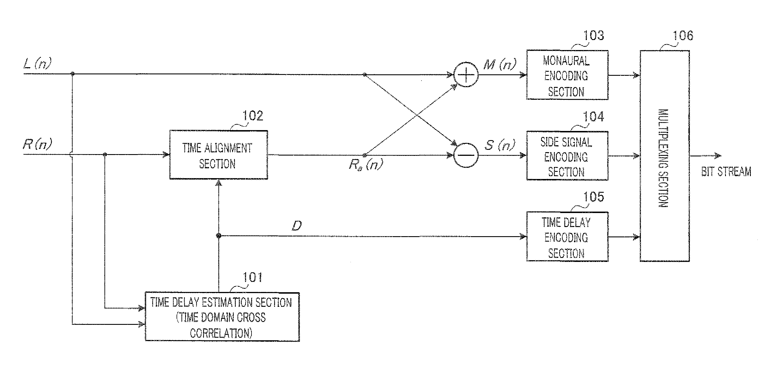
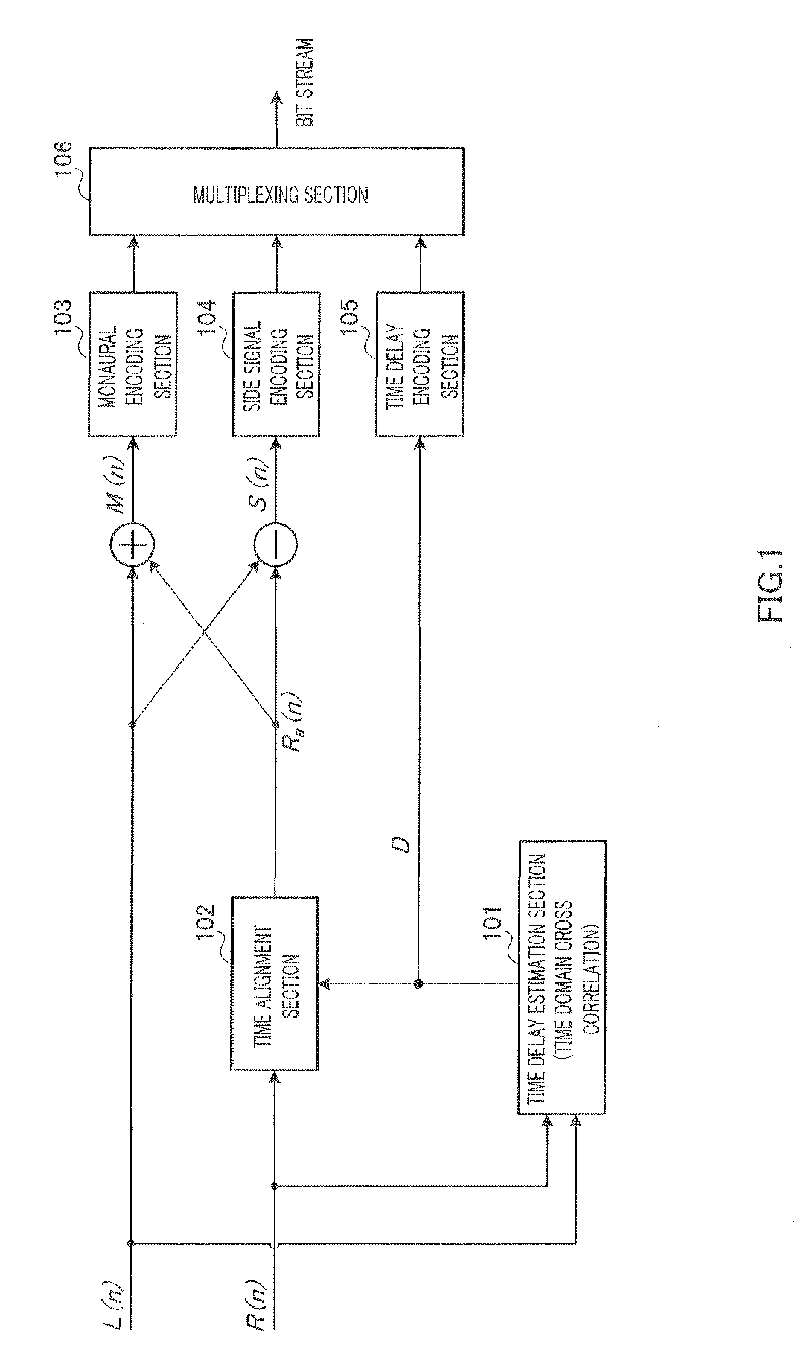
[0108]FIG. 4 is a block diagram illustrating a configuration of an encoding apparatus which estimates a time delay by applying a peak tracking method. Also, FIG. 5 is a block diagram illustrating a configuration of a decoding apparatus which estimates a time delay by applying a peak tracking method.

[0109]In an encoding process shown in FIG. 4, peak tracking section 401 estimates time delay D corresponding to a time delay between left channel signal L(n) and right channel signal R(n) of a stereo signal by using the peak tracking method.

[0110]Time delay encoding section 405 encodes time delay D, and multiplexing section 406 multiplexes encoded parameters so as to form a bit stream.

[0111]Time alignment section 402 aligns right channel signal R(n) according to time delay D. Temporally aligned right channel signal is denoted by Ra(n).

[0112]Down mix is performed on the temporally aligned signals according to equation 12.

Equation12{M(n)=L(n)+Ra(n)S(n)=L(n)-Ra(n)[12]

[0113]From equation 12, ...

embodiment 2

Variation of Embodiment 2

[0192]In Variation of Embodiment 2, before division into a plurality of sub frames, L(n) and R(n) are aligned according to derived time delay D.

[0193]FIG. 19 is a block diagram illustrating Variation of the configuration of the peak tracking section of Embodiment 2.

[0194]In FIG. 19, alignment section 1901 aligns input signals L(n) and R(n) according to derived time delay D (alignment section 1901 aligns R(n) as an example in FIG. 19). Frame division section 1902 divides aligned signals L(n) and Ra(n) into a plurality of sub frames. Here, the number of sub frames is denoted by N.

[0195]Peak tracking sections 1903, 1904, and 1905 obtain sub-frame time delays D0 to DN-1 by applying the peak tracking. Time-delay validity checking section 1906 checks on the validity of frame time delay D by using sub-frame time delays D0 to DN-1. In a case where the number of sub-frame time delays exceeding the predetermined value is larger than M (M can be a predetermined value o...

embodiment 3

[0197]In Embodiment 3, two different time delays are derived. One time delay is derived by the peak tracking method of momentarily tracking a time delay. The other time delay is derived by another time delay estimation method (for example, a low-passed cross correlation method introduced in Non-Patent Literature 3) of more stably tracking a time delay. Between the peak tracking method and the other method, a final time delay is selected.

[0198]FIG. 20 is a block diagram illustrating a configuration of an encoding apparatus of Embodiment 3. Most of the encoding apparatus shown in FIG. 20 is identical to the encoding apparatus of Embodiment 1 shown in FIG. 4. In FIG. 20, identical components to those in FIG. 4 are denoted by the same reference symbols, and a description thereof is omitted. Peak tracking section 2002 estimates time delay D′ by the peak tracking method, and another time delay estimation section 2001 derives time delay D″ by another time delay estimation method. Switch 20...


PUM


Abstract

Disclosed is a stereo acoustic signal encoding apparatus in which the signal quality does not deteriorate if there are a plurality of sound sources. A peak tracing unit (401) splits frames of a right channel signal and a left channel signal into a plurality of sub frames; detects the peaks of wave shapes of the split sub frames; and estimates a frame delay time D for each frame of the right channel signal and the left channel signal by comparing the positions of the detected peaks. A time adjusting unit (402) adjusts the time of the right channel signal on the basis of the frame time delay D. A down-mix operation is carried out using the right channel signal which has been subjected to the time adjustment and the left channel signal to generate a mono signal and a sub signal. A mono signal encoding unit (403) encodes the mono signal. A sub signal encoding unit (404) encodes the sub signal. The time delay encoding unit (405) encodes the frame time delay D.

Description

TECHNICAL FIELD[0001]The present invention relates to a stereo acoustic signal encoding apparatus, a stereo acoustic signal decoding apparatus, and methods for the same.BACKGROUND ART[0002]With a global drift towards broadband, expectations of users for communication systems have increased from just clarity to stereo feeling and naturalness. Accordingly, stereo acoustic sound signals have been provided as a trend. As a result, an effective encoding method has been desired for storing and transmitting stereo acoustic sound signals.[0003]As the stereo encoding method, for example, there are a number of stereo encoding methods which adopt Mid-Side (sum-difference) (hereinafter referred to as M / S) and use the redundancy of stereo included in stereo signals, like extended adaptive multi-rate-wideband (AMR-WB+) (for example, Non-Patent Literature 1).[0004]In M / S stereo encoding, in many cases, since a correlation between two channels is considerably high, the sum and difference between tw...

Claims


Application Information

Patent Timeline
IPC IPC(8): G10L19/00G10L19/008
CPCG10L19/008
Inventor LIU, ZONGXIANCHONG, KOK SENG
Owner III HLDG 12 LLC
Why Eureka
Try Eureka