Illuminating device

a technology of illumination device and base, which is applied in the direction of instruments, lighting and heating equipment, fibre light guides, etc., can solve the problem of less power consumption, and achieve the effect of saving the volume of the base and having cooling efficiency

Active Publication Date: 2011-12-01
CORETRONIC
View PDF0 Cites 48 Cited by
  • Summary
  • Abstract
  • Description
  • Claims
  • Application Information

AI Technical Summary

Benefits of technology

[0007]The invention provides an illuminating device, which may h

Problems solved by technology

The LED consumes less power and m

Method used


Image

  • Illuminating device
  • Illuminating device
  • Illuminating device

Examples


Embodiment Construction

[0023]It is to be understood that other embodiment may be utilized and structural changes may be made without departing from the scope of the invention. Also, it is to be understood that the phraseology and terminology used herein are for the purpose of description and should not be regarded as limiting. The use of “including,”“comprising,” or “having” and variations thereof herein is meant to encompass the items listed thereafter and equivalents thereof as well as additional items. Unless limited otherwise, the terms “connected,”“coupled,” and “mounted,” and variations thereof herein are used broadly and encompass direct and indirect connections, couplings, and mountings.

[0024]It should be also noted that the invention is not just limited to the provided embodiments. In addition, the embodiments may also be properly combined into other embodiments.

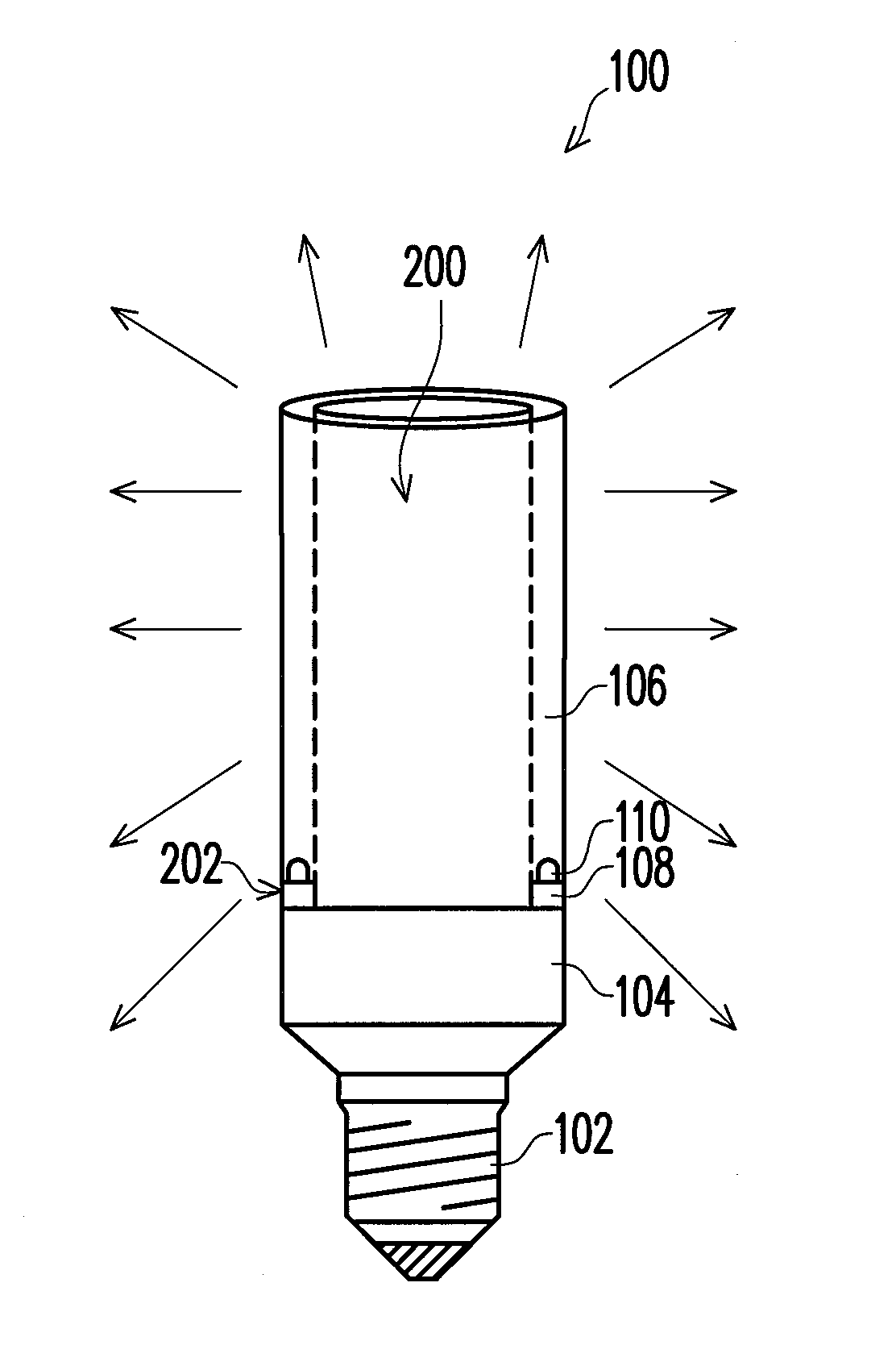
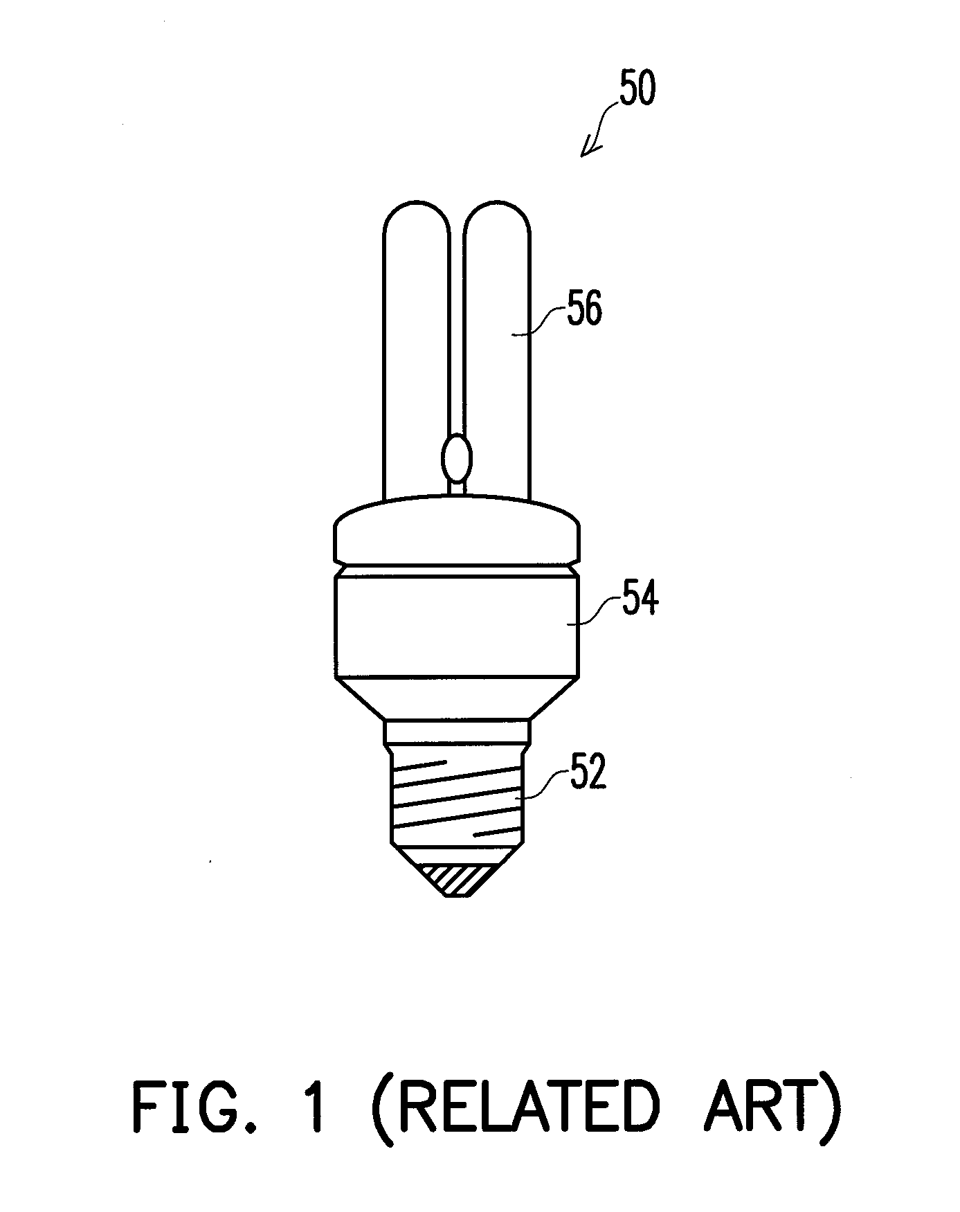
[0025]FIG. 2 is a drawing, schematically illustrating a perspective structure of an illuminating device, according an embodiment of the ...


PUM


Abstract

An illuminating device includes a tubular light guide, a plurality of light-emitting devices, and a base. The tubular light guide has a light input edge and an inner space. The light-emitting devices are distributed at the light input edge to provide lights into the tubular light guide. The base supports the light-emitting devices and the tubular light guide. The base also has an electronic circuit to provide power to the light-emitting devices. The base has at least one air circulation hole for connecting an outer space with the inner space.

Description

BACKGROUND OF THE INVENTION[0001]1. Field of Invention[0002]The invention related to illuminating device based on LED with air cooling channel.[0003]2. Description of Related Art[0004]The illuminating device has various applications. There are various mechanisms to produce the illuminating light, as known in the conventional art. FIG. 1 is a drawing, schematically illustrating the conventional lamp. In FIG. 1, the conventional lamp 50 includes a power connection structure 52, a base 54, and a light tube 56. The power connection structure 52 is used to connect to the power source. The base 54 has electric circuit to convert the external power to the operation voltages for the light tube 56. The light tube 56, filled with the gas, generates the illuminating light under the operation voltages.[0005]The lamp 50 in FIG. 1 consumes the power. Recently, the illuminating device based on LED (light-emitting diode) has been proposed. The LED consumes less power and may replace the conventiona...

Claims


Application Information

Patent Timeline
IPC IPC(8): H01J17/34
CPCF21K9/135F21K9/52F21V29/004F21V29/83F21Y2103/022G02B6/001F21Y2101/02G02B6/0038F21K9/232F21K9/61F21Y2103/33F21Y2115/10
Inventor WANG, WEI-CHIHCUSTODIS, UDOCHANG, WEN-CHIAO
Owner CORETRONIC
Why Eureka
Try Eureka