Test Apparatus with Sector Conveyance Device

a conveyancing device and test apparatus technology, applied in the field of test apparatus, can solve the problems of inability to reduce the volume of the apparatus, serious consequences and a large amount of damage, and the driver might suffer from life danger, so as to reduce the cost of operation, reduce the cost, and reduce the occupied space.

Inactive Publication Date: 2015-01-22
CHROMA ATE
View PDF7 Cites 15 Cited by
  • Summary
  • Abstract
  • Description
  • Claims
  • Application Information

AI Technical Summary

Benefits of technology

[0013]The present invention attempts to provide a test apparatus sector conveyance device, wherein the sector conveyance device is mounted pivotably by a pivot, such that a test device, a sector conveyance device and a transferring device may share the same operating space. With the cooperation of the test device, the sector conveyance device and the transferring device, during a period in which the test device performs a test operation, the sector conveyance device, in conjunction with the transferring device, transfers a tested electronic component out of the sector conveyance device, and feeds a new electronic component into the sector conveyance device. With such a structure, the occupied space is reduced significantly on one hand, and the energy loss in operating process may be reduced significantly on the other hand, together with reducing the cost necessary in testing process.

Problems solved by technology

Severely, the electronic components on cars may malfunction in a snow weather or on a highway of desert, such that drivers might suffer from life danger.
In the application of electronic components to the military equipment or weather prediction, serious consequences and a large amount of damages might occur due to malfunction of some of the electronic components.
There are following problems derived from the existing test apparatus.
The volume of the apparatus cannot be reduced, such that the volume of the thermal insulation chamber is giant accordingly because each of the thermally conditioning device and the test device needs an independent space.
Subsequently, the temperature control and humidity control inside the thermal insulation chamber mean a large amount of energy consumption, such that the test cost increases accordingly.
Furthermore, if the electronic components under a low temperature test are revealed to normal temperature air with a certain humidity, moisture in the normal temperature air will be condensed rapidly onto the surfaces of the electronic components due to the contact with the low temperature electronic components, and even result in frosting.
From above, it is recognized that the structure space of the conventional test apparatus cannot be reduced, and the space issue and high cost of the apparatus cannot be improved.

Method used


Image

  • Test Apparatus with Sector Conveyance Device
  • Test Apparatus with Sector Conveyance Device
  • Test Apparatus with Sector Conveyance Device

Examples


Embodiment Construction

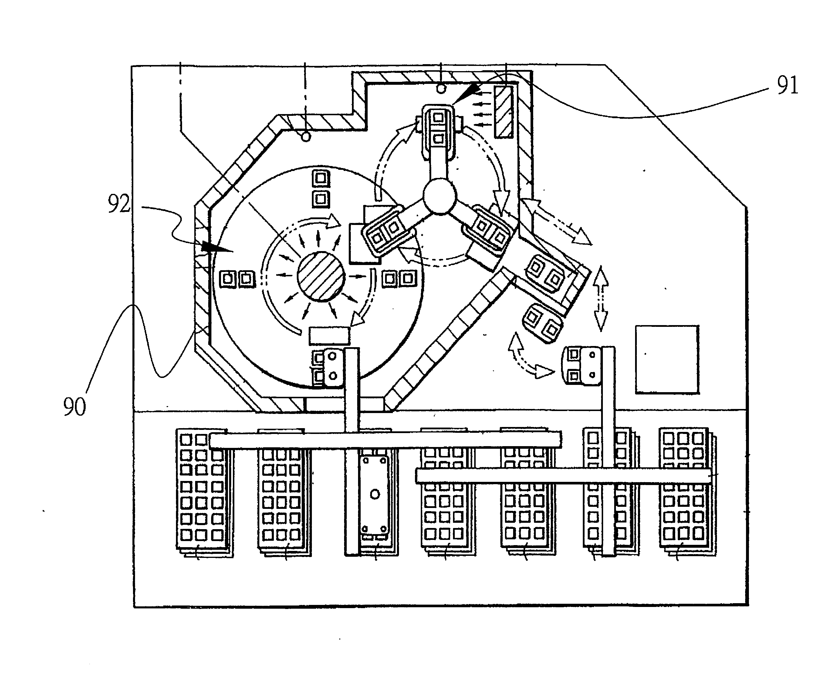
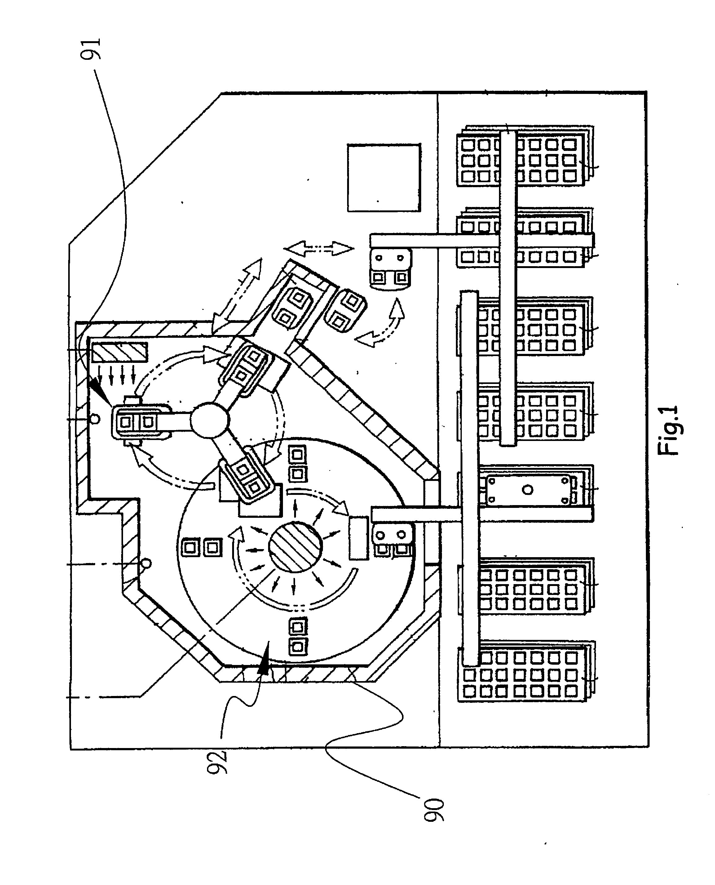
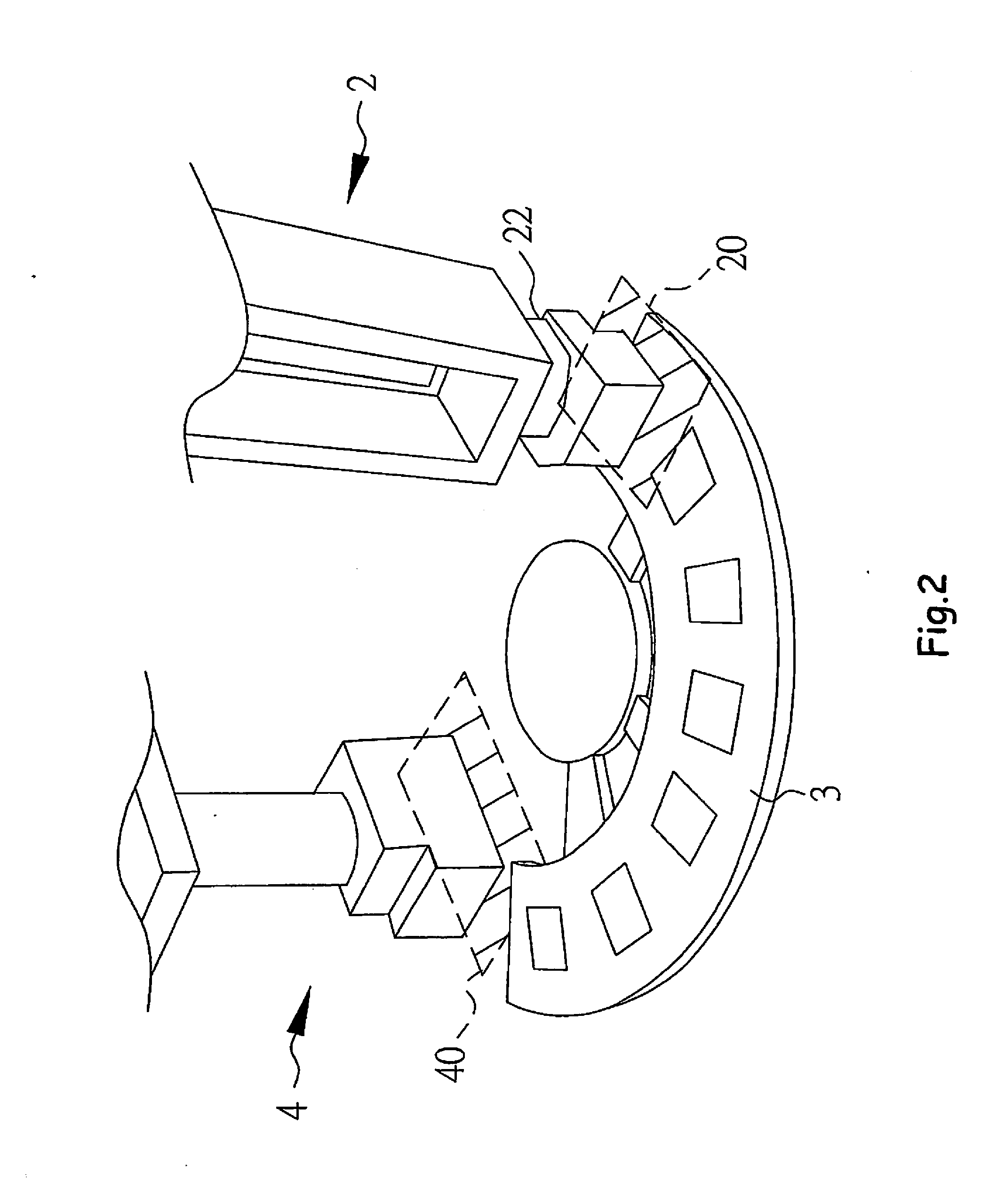
[0022]FIG. 2 shows a test apparatus of the present invention. The apparatus includes a transferring device 2 arranged in correspondence to a transferring location 20; a test device 4 arranged in correspondence to a test location 40; and a sector conveyance device 3 pivoted between the transferring location 20 and the test location 40. At first, the transferring device 2 utilizes a transferring arm 22 to transfer electronic components to be tested onto the sector conveyance device 3 on standby in the transferring location 20. For simplicity, in the following description, the electronic components are exemplified as integrated circuits (ICs).

[0023]As shown in FIG. 3, a plurality of soaking buffers 31 in form of containing grooves are formed on the sector conveyance device 3. Each soaking buffer 31 is provided with a heat exchanger module 32 at the bottom, and may receive an IC 6 to be tested. The IC 6 is brought in contact with the heat exchanger module 32 and thermally conditioned (f...


PUM


Abstract

A test apparatus includes a sector conveyance device provided with a plurality of soaking buffers, the soaking buffers being used to carry electronic components, the sector conveyance device being mounted pivotably by a pivot and moved between a test location and a transferring location; a transferring device arranged in correspondence to the transferring location, used to transfer a plurality of electronic components into or out of the sector conveyance device; and a test device arranged in correspondence to the test location for testing electronic components, the electronic components being transferred into the sector conveyance device after test.

Description

BACKGROUND OF THE INVENITON[0001]1. Field of the Invention[0002]The present invention relates to a test apparatus, particularly to a test apparatus with a sector conveyance device.[0003]2. Description of the Related Art[0004]With the wide application of electrical products, electronic components thereof are usually requested to work in severe environments. Vendors have to ensure the endurance of the electronic components, such as Integrated circuits (ICs), with respect to various temperatures in order to prevent the electronic components from failure in critical situations. Severely, the electronic components on cars may malfunction in a snow weather or on a highway of desert, such that drivers might suffer from life danger. In the application of electronic components to the military equipment or weather prediction, serious consequences and a large amount of damages might occur due to malfunction of some of the electronic components. Thus, in order to guarantee stability of electron...

Claims


Application Information

Patent Timeline
Patent Type & Authority Applications(United States)
IPC IPC(8): G01R31/28
CPCG01R31/2893G01R31/2867G01R31/2849G01R31/2874H01L21/67
Inventor LEE, YI-CHIAOWU, XIN-YI
Owner CHROMA ATE
Why Eureka
Try Eureka