Shaped Charge Casing

a charge casing and shape technology, applied in the field of shape charge casings, can solve the problems of occupying a large volume and less space for other equipment to be taken, and achieve the effects of reducing manufacturing costs, reducing the possibility of loss or failure of a small component, and being convenient to us

Active Publication Date: 2014-03-06
THE SEC OF STATE FOR DEFENCE IN HER BRITANNIC MAJESTYS GOVERNMENT OF THE UK OF GREAT BRITAIN & NORTHERN IRELAND
View PDF0 Cites 13 Cited by
  • Summary
  • Abstract
  • Description
  • Claims
  • Application Information

AI Technical Summary

Benefits of technology

[0007]The two part design is simple, easy to use, removes the possibility of the loss or failure of a small component and keeps manufacturing costs to a minimum. The design of the invention allows several lid and body portions to be nested in succession. Where nesting is used here to mean a part of one body fits inside another body so as to save volume. The same also applies to lids being nested. The body portion of the shaped charge has an internal lip to hold the shaped charge liner in place whilst explosive material such as PE4 can be packed onto the liner. Different liners can be simply inserted without changing other parts of the charge. A tapered shape design of the body and lid portions makes nesting easier.
[0008]The lid portion may be shaped as a cone. Preferably a detonator holding means can be incorporated by the lid being designed in the shape of an inverted funnel. The narrow neck of the lid can hold in position a standard demolition detonator (electric or plain) or a detonating cord booster. The detonator is simply inserted and will remain in place when subjected to normal stresses for an emplaced explosive charge. Providing chamfered edges on the lid makes it easier for stacking one lid onto another. The body of the shaped charge may be designed as a truncated cone. The tapered shape of the body reduces the distance between the bulk of the explosive and the target i.e. the standoff distance, maximizing blast damage. This is advantageous when explosive blast damage is required as well as shaped charge effects. The shaped charge being in two parts allows the easy packing and removal of explosive material within the lid and the body. The tapering encourages homogenous filing with no air gaps next to the liner, which ensures efficient jet formation. The combined shape of the body and lid portions is conducive to rapid, high quality stemming and simplifies manual stemming of the charge. The external step provided on the outside of the body also enables easy stacking of one body on top of another, with no high-stress points that might cause deformation.
[0009]The lid and body portions are connected together with attachment means such as clips. If the casing is based on a cylindrical configuration then the attachment means is preferably a cooperating screw thread. This has the advantage that when screwing together of the body and lid portions, this ensures that the explosive is compressed to ensure efficient formation of the shaped charge jet.
[0010]The lid and body portions may be formed of polymeric material. Preferably the lid and body of the shaped charge will be comprised of structural polyurethane foam. This is a lightweight material that is easy to manufacture at low cost. This material is considered non-fragmenting which allows a very low weapon danger area when compared with other commonly used shaped charge casing materials. It is also structurally strong enough to allow stacking and carriage of several shaped charges without the additional need for protective packaging. Typically the user will carry the stacked charges in a back pack where volume is limited, allowing other equipment to be packed. Other materials such as syntactic foam, thin wall, or low resin content reinforced polymers are alternatives that can be used.
[0011]A further benefit of the invention is that the liner can be assembled with the casing for nesting, this facilitates quicker hand stemming for the user.

Problems solved by technology

If the user wishes to carry several shaped charge casings on his person, it means a considerable volume is taken up and thus there is less space available for other equipment to be taken.

Method used


Image

  • Shaped Charge Casing
  • Shaped Charge Casing

Examples


Embodiment Construction

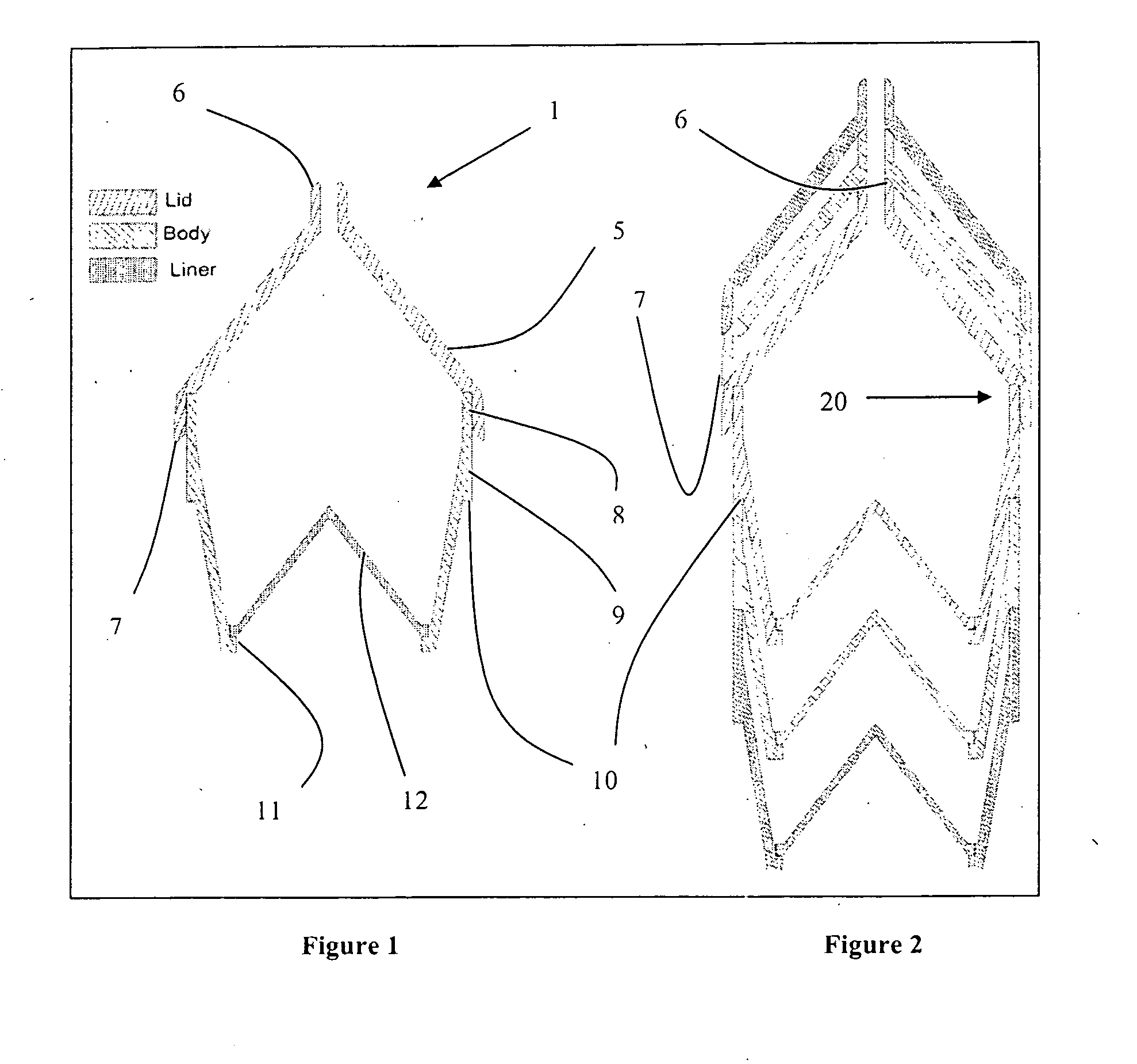
[0015]FIG. 1 shows a cross sectional view of a nestable shaped charge casing 1 as assembled. A key is provided to distinguish the components of FIG. 1 only. A lid portion 5 is shaped as an inverted funnel and edges 6 and 7 are chamfered to enable several lid portions to be stacked efficiently (see FIG. 2). The lid portion 5 is connected at point 8 to a body portion 9. The means of connection is a screw thread. The body portion 9 has a step 10 to enable several body portions to be nested efficiently (see FIG. 2). The body portion 9 also has a lip 11 to allow a shaped charge liner 12 to be fitted.

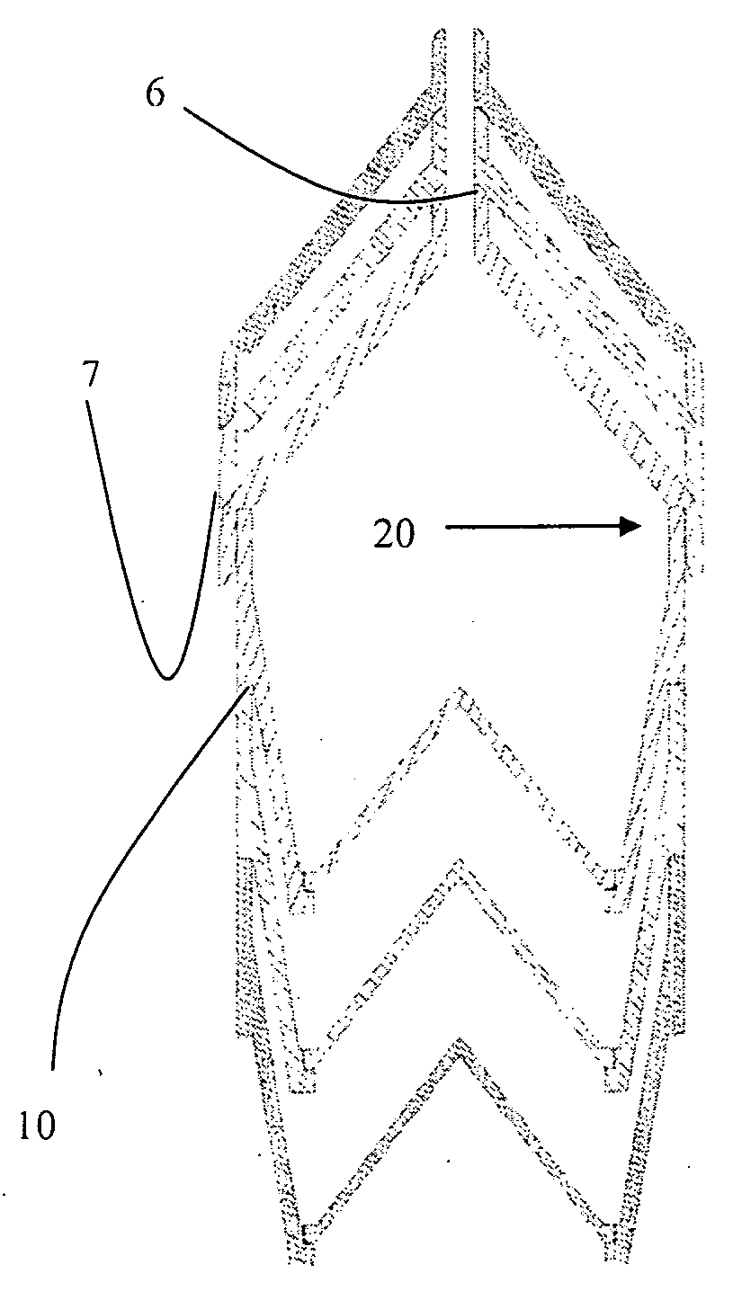
[0016]FIG. 2 shows a cross sectional view of several nestable shaped charge casings. The nestable shaped charge casing 20 is positioned centrally and is assembled. Two further lid portions are shown stacked above and two further body portions are shown stacked beneath shaped charge casing 20. The chamfered edges 6 and 7 and step 10 allow the lid and body portions to mate effectively.

[0017]Ass...


PUM


Abstract

A shaped charge casing 1 designed to be nested to reduce overall volume, which benefits storage or carriage. A lid portion 5 is connected at 8 to a body portion 9 by means of a screw thread. A shaped charge liner 12 can be positioned onto lip 11. The lid portion 5 and body portion 9 can be separated to allow filling or unpacking of explosive material.

Description

FIELD OF INVENTION[0001]This invention relates to shaped charge cases, in particular shaped charge cases that can be nested and more specifically hand stemmed shaped charge cases that are nestable to reduce volume for carriage without detriment to the performance of the casing.BACKGROUND TO THE INVENTION[0002]A shaped charge is an explosive charge shaped to focus the effect of the explosive's energy. A typical device consists of a solid cylinder of explosive with a metal-lined conical hollow in one end and a central detonator at the other end contained within a casing. The enormous pressure generated by the detonation of the explosive drives the liner contained within the hollow cavity inward to collapse upon its central axis. The resulting collision forms and projects a high-velocity jet of metal forward along the axis.[0003]Shaped charges are frequently used as warheads in anti-tank missiles (guided and unguided) and also gun-fired projectiles (spun and unspun), rifle grenades, mi...

Claims


Application Information

Patent Timeline
Patent Type & Authority Applications(United States)
IPC IPC(8): F42B12/10
CPCF42B12/10F42B1/028F42B1/02
Inventor MCLEAN, STEPHEN JAMESKIRKPATRICK, DOUGLASCHAPMAN, NIGEL
Owner THE SEC OF STATE FOR DEFENCE IN HER BRITANNIC MAJESTYS GOVERNMENT OF THE UK OF GREAT BRITAIN & NORTHERN IRELAND
Why Eureka
Try Eureka