
Diagnostic device system

a diagnostic device and battery technology, applied in diagnostic devices, electric vehicles, transportation and packaging, etc., can solve the problems of reducing the charge amount of the rechargeable battery used in the diagnostic device, increasing the charge amount of the rechargeable battery, and unable to use the diagnostic device in the destination, so as to achieve the effect of reducing the weight of the battery

Active Publication Date: 2011-12-01
FUJIFILM CORP
View PDF9 Cites 5 Cited by
  • Summary
  • Abstract
  • Description
  • Claims
  • Application Information

AI Technical Summary

Benefits of technology

[0007]It is an object of the invention to reduce the weight of the rechargeable battery.

Problems solved by technology

However, in the conventional art, for example, when a diagnostic device is used in visiting a personal home or visiting a care home, the charge amount of the rechargeable battery used in the diagnostic device decreases in a case that there are plural destinations, and the diagnostic device cannot be used in the destinations.
Thus, the charge amount of the rechargeable battery needs to be increased and the weight of the conventional rechargeable battery has been heavy.

Method used


Image

  • Diagnostic device system
  • Diagnostic device system
  • Diagnostic device system

Examples


Embodiment Construction

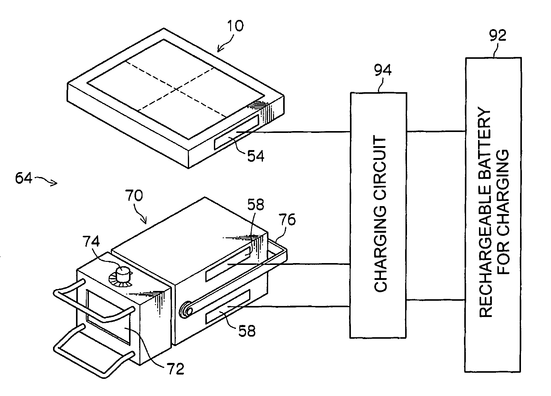
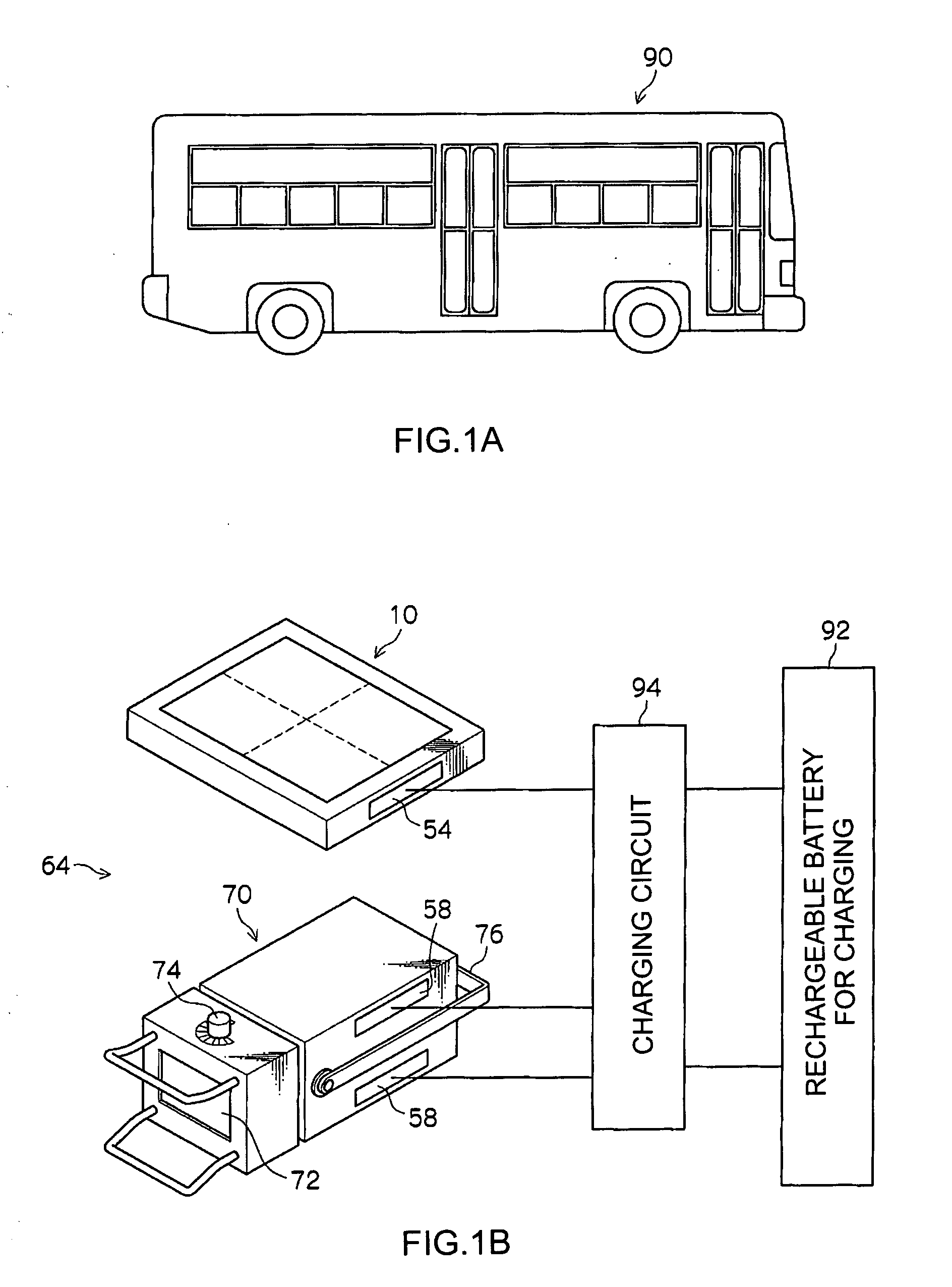
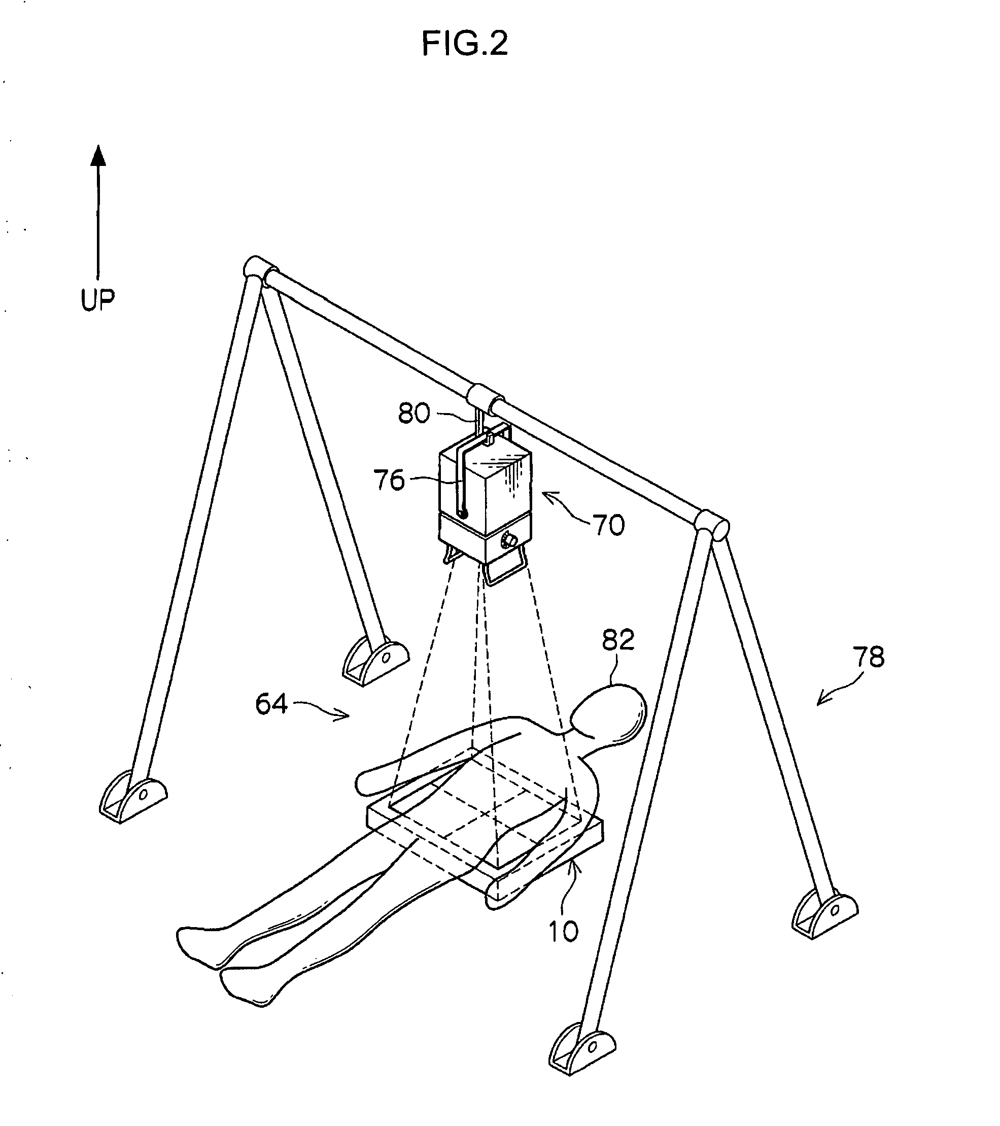
[0038]One example of a diagnostic device system 64 according to a first exemplary embodiment of the invention will be described with reference to FIG. 1A, FIG. 1B to FIG. 7. The arrow UP in the Figures indicates the upward direction.

[0039](Entire Structure)

[0040]As shown in FIG. 5, a radiographic element 12 is provided inside a housing 18 of a portable radiographic apparatus 10 (so-called cassette) as one exemplary diagnostic device provided in the diagnostic device system 64 (see FIG. 1B). The radiographic element 12 includes an upper electrode, a semiconductor layer, and a lower electrode, and is provided with, in a two-dimensional shape, plural pixels 20 each including a sensor portion 14 for receiving light and accumulating charges and a TFT switch 16 for reading out the charges accumulated in the sensor portion 14.

[0041]The radiographic element 12 is provided with plural scan wirings 22 for powering on or off the TFT switches 16 and plural signal wirings 24 for reading out the ...


PUM


Abstract

A diagnostic device system has a weight-reduced rechargeable battery. When a portable radiographic apparatus and a portable X-ray source are carried to and used for imaging at a private home or a care home, the portable radiographic apparatus and the portable X-ray source are loaded on an automobile. When the charge amount of rechargeable batteries for operation housed in the portable radiographic apparatus or the portable X-ray source loaded on the automobile is low, or when there are plural destinations and the charge amount of the rechargeable batteries becomes low, a rechargeable battery for charging mounted on the automobile is used to charge the rechargeable batteries for operation while traveling. Because the rechargeable batteries for operation are charged while traveling, a large number of rechargeable batteries for operation does not need to be charged in advance, whereby the weight of the rechargeable batteries for operation can be reduced.

Description

CROSS-REFERENCE TO RELATED APPLICATION[0001]This application claims priority under 35 USC 119 from Japanese Patent Application No. 2010-121860 filed on May 27, 2010, the disclosure of which is incorporated by reference herein.BACKGROUND[0002]1. Technical Field[0003]The present invention relates to a diagnostic device system used for diagnosis of diseases of humans or animals.[0004]2. Related Art[0005]A radiological image detector (diagnostic device) described in Japanese Patent Application Laid-Open (JP-A) No. 2006-208303 is mounted with a rechargeable battery. The radiological image detector is configured to operate with electric power of the battery.[0006]However, in the conventional art, for example, when a diagnostic device is used in visiting a personal home or visiting a care home, the charge amount of the rechargeable battery used in the diagnostic device decreases in a case that there are plural destinations, and the diagnostic device cannot be used in the destinations. Thus...

Claims


Application Information

Patent Timeline
Patent Type & Authority Applications(United States)
IPC IPC(8): H02J7/00
CPCA61B6/56A61B6/44
Inventor KAMIYA, TAKESHIKITAGAWA, YUSUKEOHTA, YASUNORINAKATSUGAWA, HARUYASU
Owner FUJIFILM CORP
Learn More