
Wavelength conversion apparatus, wavelength conversion method, and optical add/drop multiplexer using the same

a wavelength conversion and wavelength technology, applied in multiplex communication, instruments, optical elements, etc., can solve the problems of high-speed response characteristics, limited operation speed of electronic circuitry, and difficulty for a single electric circuit to deal with signals of various modulations

Inactive Publication Date: 2011-12-01
FUJITSU LTD
View PDF8 Cites 22 Cited by
  • Summary
  • Abstract
  • Description
  • Claims
  • Application Information

AI Technical Summary

Problems solved by technology

However, with the wavelength conversion method of signal light using electronic circuitry, since the electronic circuitry depends on signal light modulation formats, it is difficult for a single electric circuit to deal with signals of various modulations.
There is also a problem with high-speed response characteristics because of limitation on the operating speed of the electronic circuitry.
In addition, a process of converting a signal light wavelength that keeps signal light in the form of light without using electronic circuitry may consume less electricity than a process of converting signal light wavelengths using electronic circuitry.
However, since the gain derived from the Raman effect is produced only on the long wavelength side of the signal light, the wavelength conversion using the self-frequency shift effect is unable to convert a wavelength into a wavelength on the short wavelength side.

Method used


Image

  • Wavelength conversion apparatus, wavelength conversion method, and optical add/drop multiplexer using the same
  • Wavelength conversion apparatus, wavelength conversion method, and optical add/drop multiplexer using the same
  • Wavelength conversion apparatus, wavelength conversion method, and optical add/drop multiplexer using the same

Examples


first embodiment

[0033]A wavelength conversion apparatus of a first embodiment converts a wavelength λin of input signal light into a desired wavelength λout of output signal light and outputs resultant signal light.

[0034]FIG. 3 illustrates an example of a wavelength conversion apparatus of the first embodiment. A wavelength conversion apparatus 100 illustrated in FIG. 3 includes a first wavelength converter 110, a second wavelength converter 120, a laser diode (LD) 132, a wavelength monitor 134, and an optical tap 136. The first wavelength converter 110 includes an optical power adjuster 112, a control circuit 114, and a first nonlinear medium 116. The second wavelength converter 120 includes a second nonlinear medium 122 and an optical selector (filter) 124.

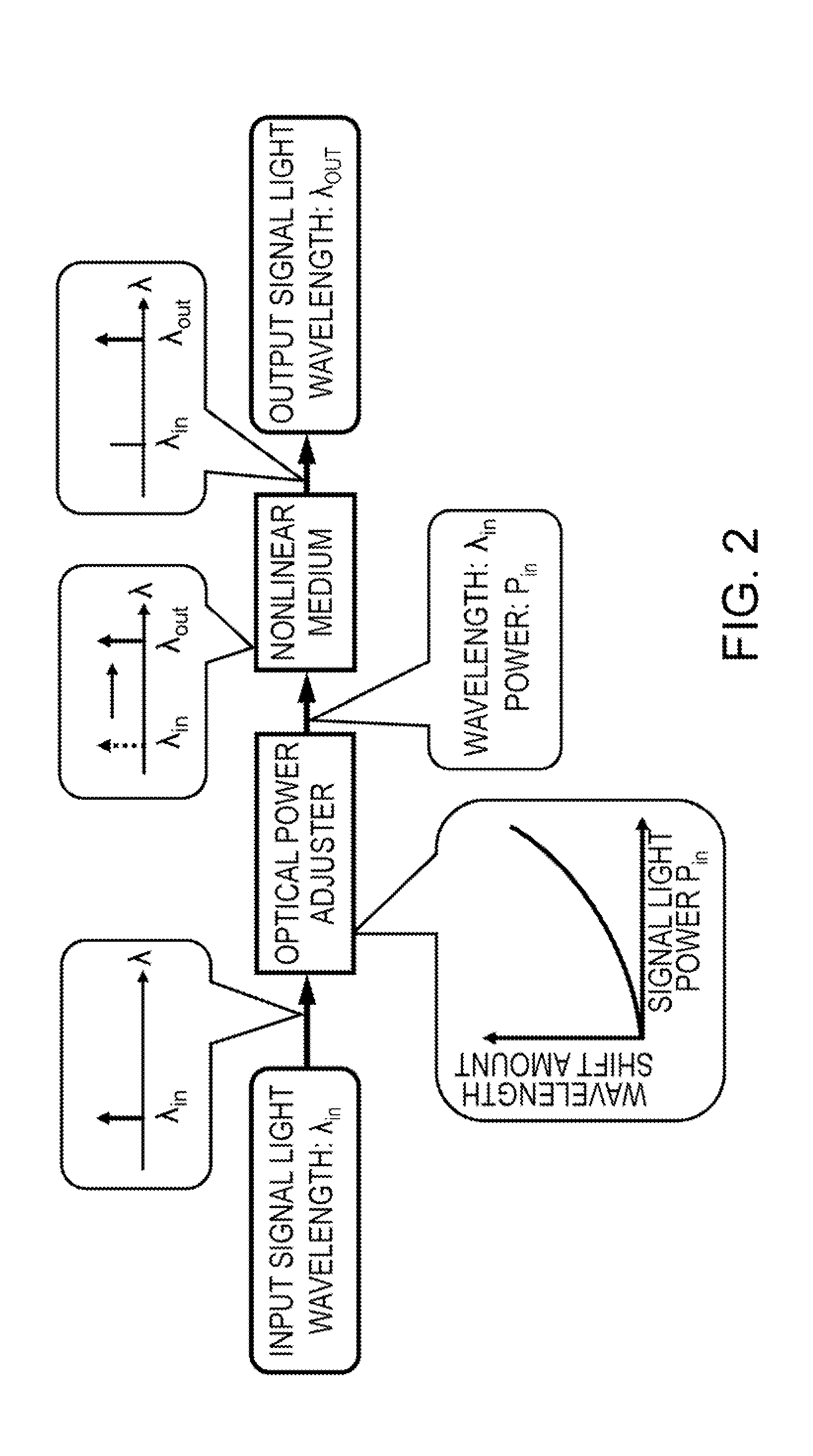
[0035]The first wavelength converter 110 converts a wavelength λin of input signal light into an intermediate wavelength λm using the self-frequency shift effect, and outputs the resultant signal light. The wavelength shift amount that is a dif...

second embodiment

[0056]Next, a second embodiment will be described. The second embodiment and the first embodiment have certain common features. Accordingly, the descriptions below are mainly dedicated to differences between the first and second embodiments and descriptions on common features will be omitted.

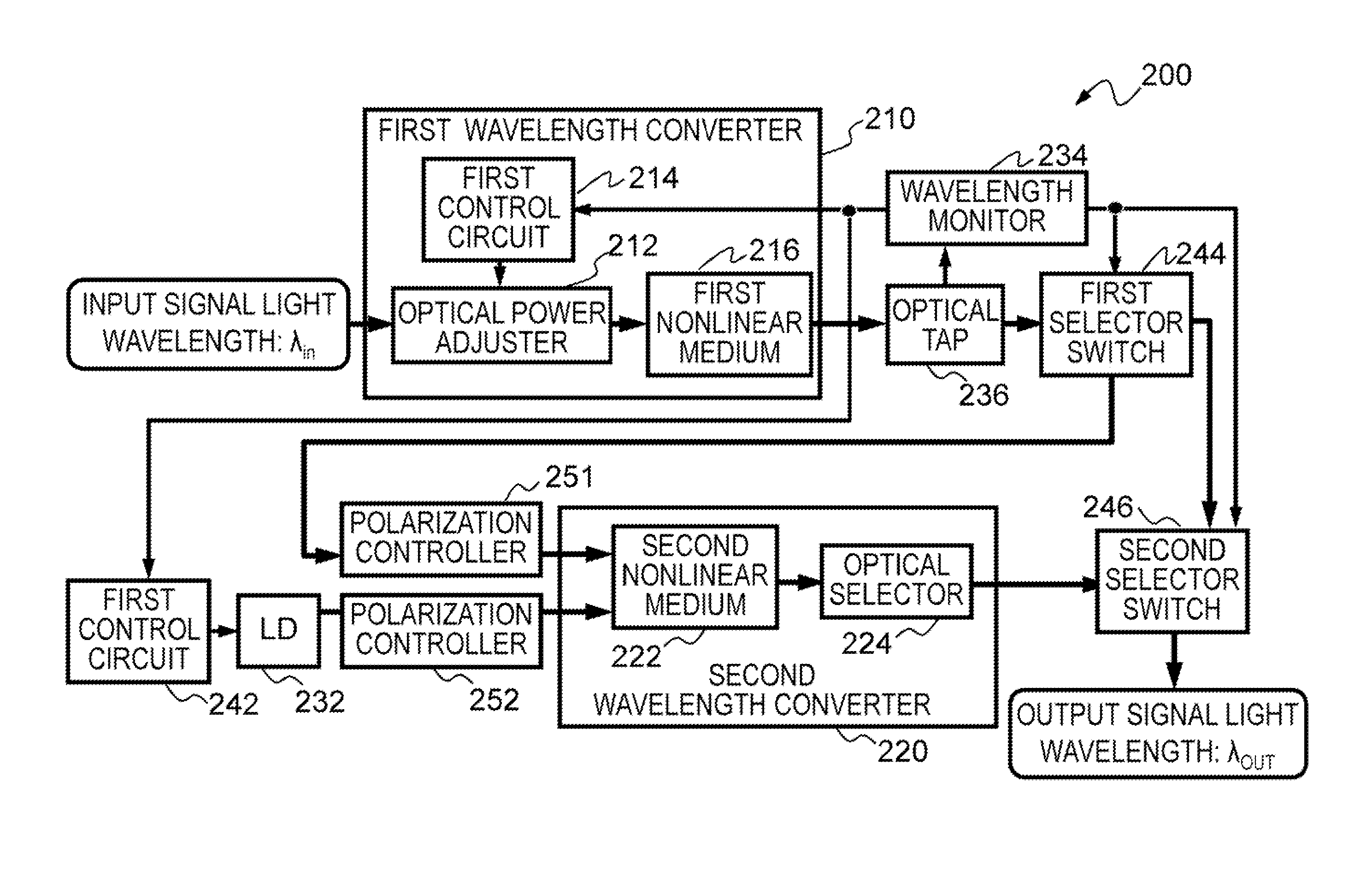
[0057]As is the case with the wavelength conversion apparatus of the first embodiment, a wavelength conversion apparatus of the second embodiment includes two wavelength converters that convert wavelengths using the self-frequency shift effect and the FWM effect. The wavelength conversion apparatus of the second embodiment converts a wavelength without wavelength conversion by the FWM effect when a wavelength λin of input signal light is shorter than a desired wavelength λout of output signal light.

[0058]FIG. 5 illustrates an example of a wavelength conversion apparatus of the second embodiment. A wavelength conversion apparatus 200 illustrated in FIG. 5 includes a first wavelength converter 210...

third embodiment

[0073]Next, a third embodiment will be described. The third embodiment and the first to second embodiments have certain common features. Accordingly, the descriptions below are mainly dedicated to differences between the third embodiment and the first to second embodiments and descriptions on common features will be omitted.

[0074]As is the cases with the wavelength conversion apparatuses of the first and second embodiments, a wavelength conversion apparatus of the third embodiment includes two wavelength converters that convert wavelengths using the self-frequency shift effect and the FWM effect. The wavelength conversion apparatus of the third embodiment performs wavelength conversion using the FWM effect before performing wavelength conversion by the self-frequency shift effect.

[0075]FIG. 7 illustrates an example of a wavelength conversion apparatus of the third embodiment. A wavelength conversion apparatus 300 illustrated in FIG. 7 includes a second wavelength converter 320, a fi...


PUM


Abstract

There is provides a wavelength conversion apparatus for converting a wavelength of input signal light and for outputting output signal light of the converted wavelength. The apparatus includes a first and a second nonlinear mediums. The first nonlinear medium receives a first input light and outputs a first output light having a wavelength which is longer than that of the first input light, the wavelength being dependent on optical power of the first input light. The second nonlinear medium receives a second input light and a light output by a light source and outputs a second output light having a wavelength dependent on the wavelengths of the second input light and the light. The first output light is input as the second input light to the second nonlinear medium or the second output light is input as the first input light to the first nonlinear medium.

Description

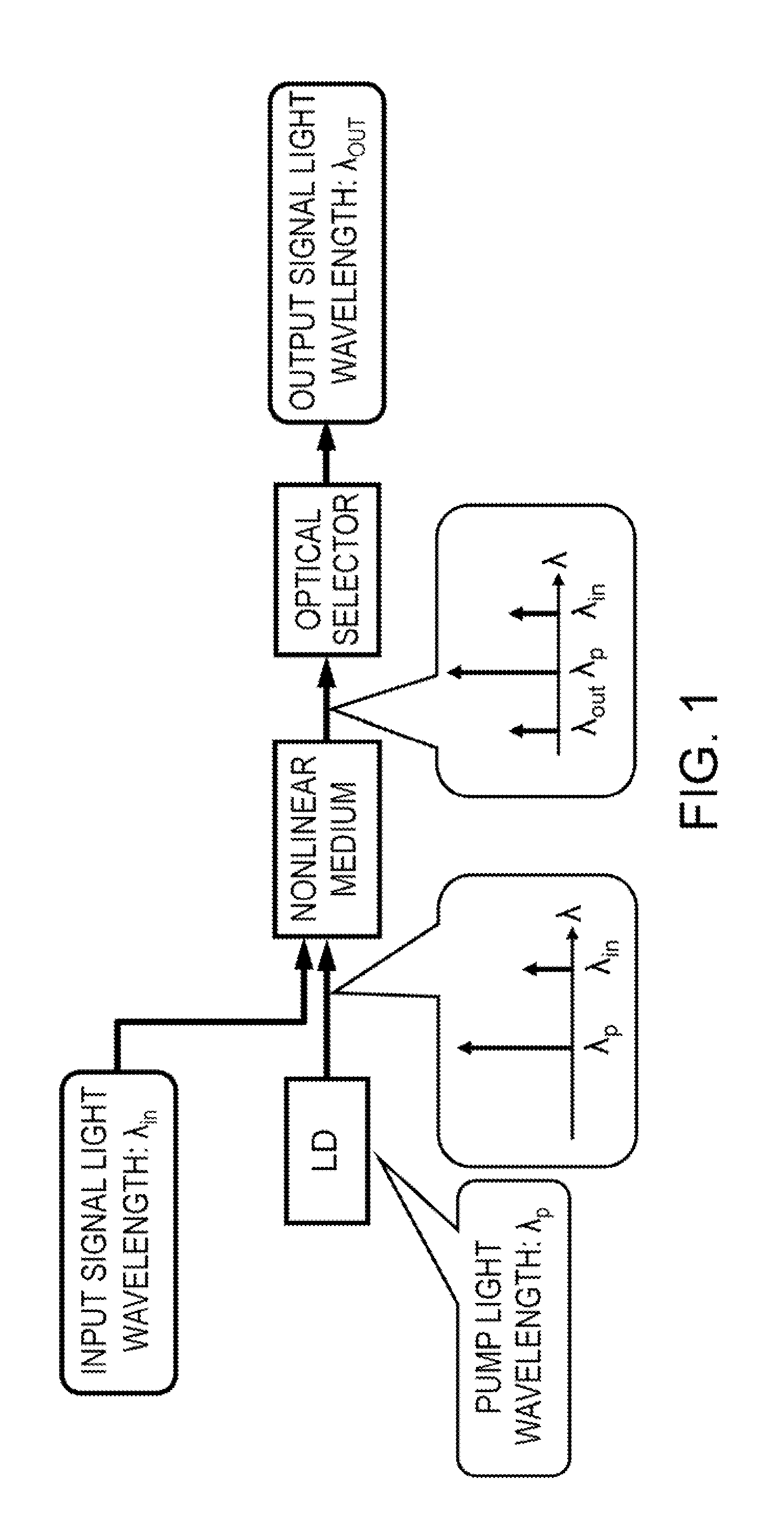
CROSS-REFERENCE TO RELATED APPLICATION[0001]This application is based upon and claims the benefit of priority of the prior Japanese Patent Application No. 2010-125145, filed on May 31, 2010, the entire contents of which are incorporated herein by reference.FIELD[0002]The embodiments discussed herein are related to a wavelength conversion apparatus, a method of converting a wavelength, and an optical add / drop multiplexer that convert a wavelength of input signal light into a desired wavelength of output signal light.BACKGROUND[0003]Wavelength conversion technology that converts wavelengths of signal light is used, for example, to effectively design and operate photonic networks. Photonic networks utilize widely used wavelength division multiplexing and use optical fiber transmission lines as signal light transmission lines. The wavelength conversion technology desirably features an independent property from modulation formats so as to operate for signals of a variety of modulation fo...

Claims


Application Information

Patent Timeline
IPC IPC(8): G02F1/35H04J14/02
CPCG02F1/3513G02F1/3532G02F1/3536H04J14/0212H04J14/02H04J14/0201H04B10/00
Inventor FUTAMI, FUMIO
Owner FUJITSU LTD
Learn More