
Optical multiplexing apparatus and optical multiplexing method

a technology of optical multiplexing and optical signal, applied in multiplex communication, electromagnetic repeaters, instruments, etc., can solve the problems of difficult multiplexing of optical signals, difficult to realize multiplexing when they are different in polarization states, and influence of nonlinear optical effect becomes a problem, etc., to achieve reliable multiplexing of a plurality of optical signals, suppressing nonlinear optical effect and crosstalk, and low cost

Inactive Publication Date: 2005-06-07
FUJITSU LTD
View PDF8 Cites 21 Cited by
  • Summary
  • Abstract
  • Description
  • Claims
  • Application Information

AI Technical Summary

Benefits of technology

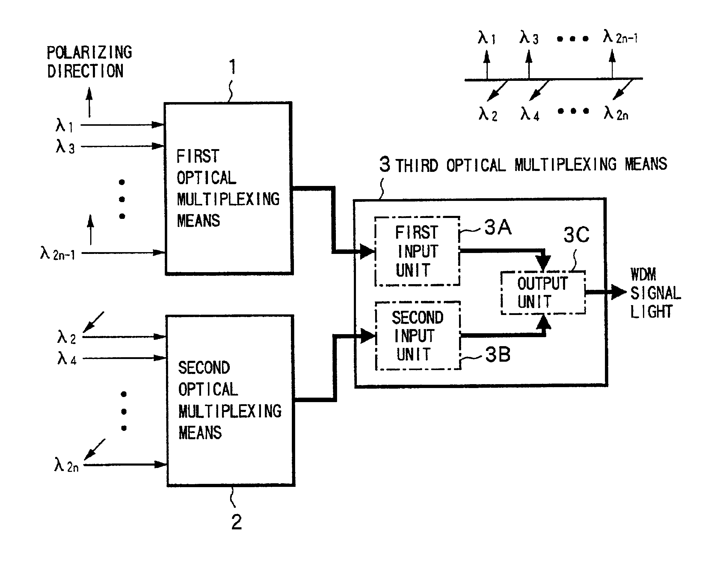
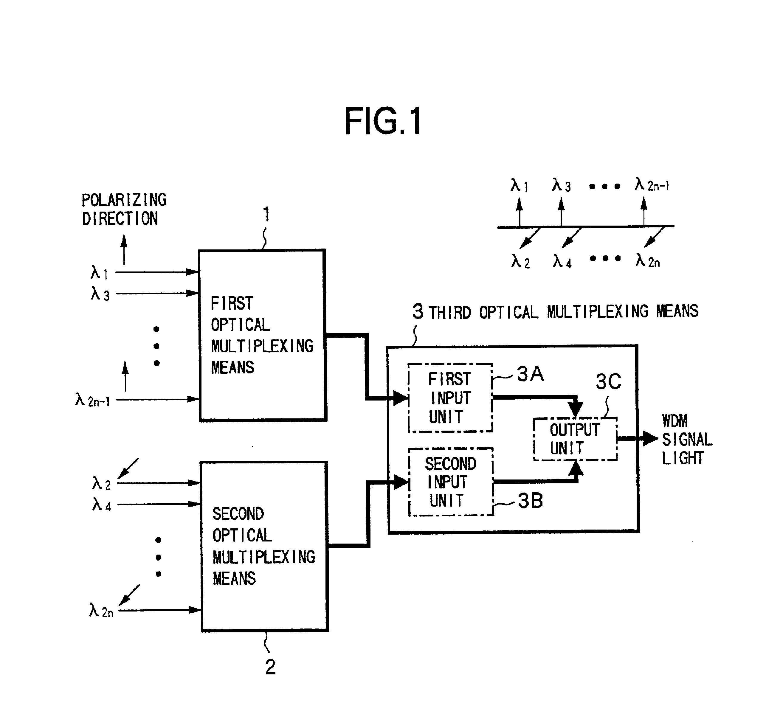
The present invention provides an optical multiplexing apparatus and method that can reliably multiplex a plurality of optical signals with narrow wavelength intervals while suppressing nonlinear optical effects and crosstalk. The apparatus includes first, second, and third optical multiplexing means for multiplexing optical signals with different wavelengths while maintaining their polarization states. The third optical multiplexing means includes filters that filter the multiplexed optical signals based on their wavelengths and band widths to output a high-quality WDM signal light. The invention can be used in optical communication systems to reliably transmit multiple optical signals with narrow wavelength intervals.

Problems solved by technology

However, when the wavelength intervals of the optical signals to be multiplexed are set to be as very narrow as, for example, 50 GHz, the influence of nonlinear optical effect becomes a problem together with the occurrence of crosstalk among the channels.
However, it is not easy to multiplex the optical signals having narrow wavelength intervals while maintaining their polarization states.
When an existing optical device is considered, such as an arrayed waveguide grating (hereinafter referred to as AWG), it is relatively easy to multiplex a plurality of optical signals in the identical polarization state while maintaining their polarization state, but it is very difficult to realize the multiplexing when they are different in polarization states.
Besides, even if an optical device is realized which is capable of multiplexing such optical signals, its cost will be very high.
Further, even if the nonlinear optical effect is relaxed by the employment of the cross polarization system, crosstalk occurs among the channels accompanying a decrease in the wavelength interval unless the optical device multiplexing the optical signals exhibits sharp filter characteristics, to deteriorate the transmission characteristics.
It is possible to decrease the influence due to the nonlinear optical effect accompanying a decrease in the wavelength interval but it is difficult to sufficiently suppress the occurrence of crosstalk among the channels.
In general, however, since the interference-film type optical devices have poor filter characteristics, the wavelength interval that can be coped with is restricted.
When the wavelength interval becomes as narrow as about 50 GHz, although the optical devices having a wavelength interval of twice as wide can be used as the first and second optical multiplexing circuits, it is impossible to avoid deterioration in the transmission characteristics due to crosstalk only by simply multiplexing a set of cross polarized optical signals without any contrivance for suppressing the crosstalk in the third optical multiplexing circuit.

Method used


Image

  • Optical multiplexing apparatus and optical multiplexing method
  • Optical multiplexing apparatus and optical multiplexing method
  • Optical multiplexing apparatus and optical multiplexing method

Examples


Embodiment Construction

[0035]An embodiment of the invention will now be described with reference to the drawings.

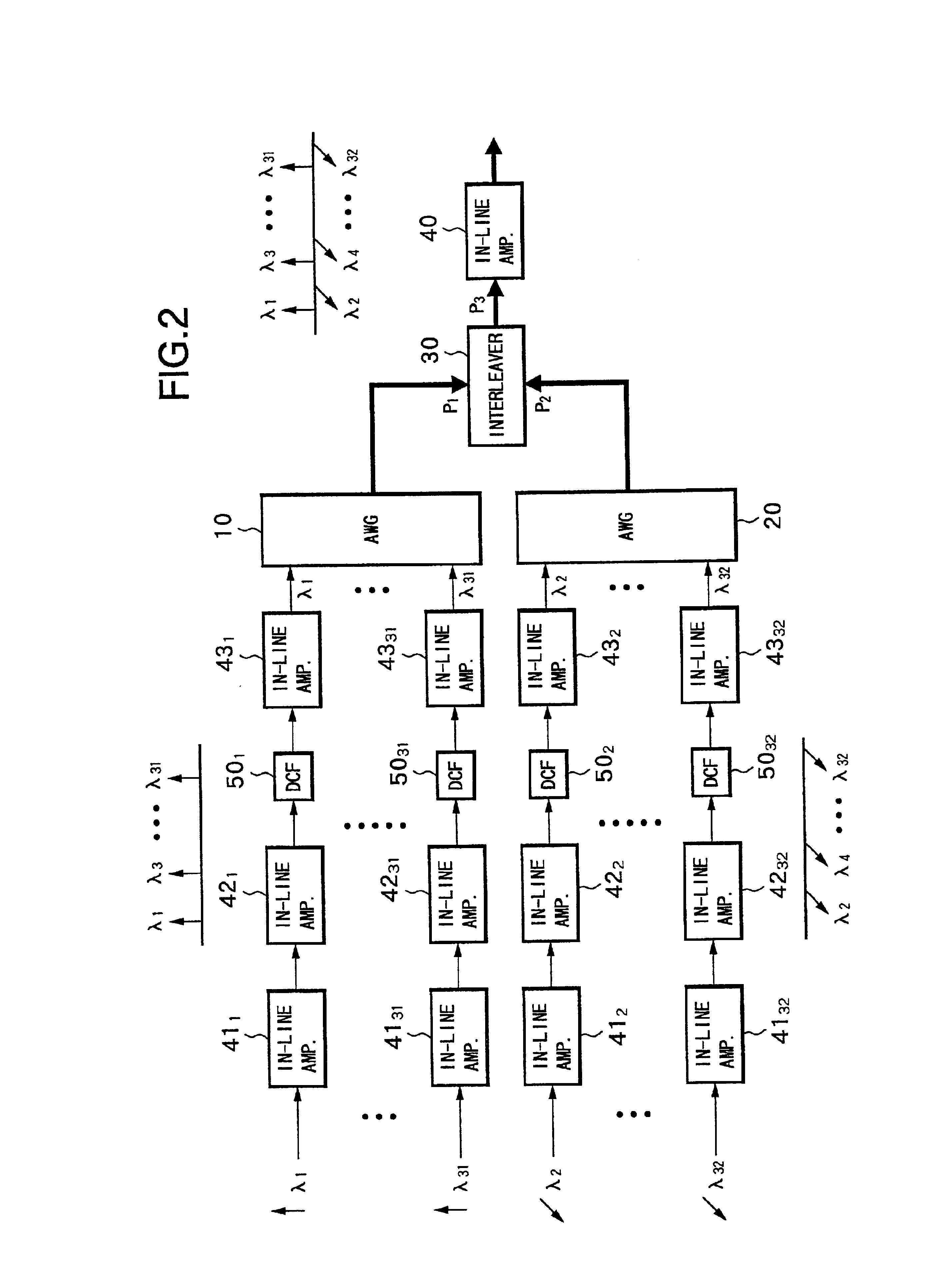
[0036]FIG. 2 is a diagram showing a constitution of an optical multiplexing apparatus according to the embodiment of the present invention.

[0037]In FIG. 2, the present optical multiplexing apparatus includes: in-line amplifiers 411 to 4132, 421 to 4232 and 431 to 4332 of a three-stage constitution for amplifying incident optical signals of a plurality of wavelengths (here, 32 waves are presumed, and their wavelengths are denoted by λ1 to λ32) for each of the wavelengths; dispersion compensation fibers (hereinafter referred to as DCFs) 501 to 5032 connected, respectively, between the in-line amplifiers 421 to 4232 of the second stage and the in-line amplifiers 431 to 4332 of the third stage; an array waveguide grating (AWG) 10 as a first optical multiplexing means 1 for multiplexing optical signals output from the in-line amplifiers 431, - - - , 4331 corresponding to wavelengths of odd numbers λ...


PUM


Abstract

An optical multiplexing apparatus of a low cost is capable of reliably multiplexing a plurality of optical signals having a narrow wavelength interval, while suppressing the nonlinear optical effect and the crosstalk, and a multiplexing method. The optical multiplexing apparatus includes a first optical multiplexer for multiplexing, among a plurality of optical signals that are input with directions of linear polarization of the neighboring wavelengths being differed to each other, optical signals having odd wavelength numbers while maintaining their polarization states. A second optical multiplexer multiplexes optical signals having even wavelength numbers while maintaining their polarization states, and a third optical multiplexer multiplexes, at an output unit thereof through first and second input units having sharp filtering characteristics, the optical signals multiplexed by the first and second optical multiplexing means, to output WDM signal light.

Description

BACKGROUND OF THE INVENTION[0001]1. Field of the Invention[0002]The present invention relates to an optical multiplexing technology for multiplexing a plurality of optical signals of different wavelengths. More particularly, the invention relates to an optical multiplexing apparatus for reliably multiplexing a plurality of optical signals having narrow wavelength intervals with a simple constitution, and to an optical multiplexing method.[0003]2. Description of the Related Art[0004]In the optical communications In recent years, it has been desired to increase the transmission capacity, and a wavelength division multiplexing (WDM) system has been developed as one of the means. In the optical transmission system according to the WDM system, in general, optical signals of plural wavelengths are transmitted through a single optical transmission line, and are demultiplexed or multiplexed in accordance with their wavelengths while being amplified through an optical amplifier so as to be t...

Claims


Application Information

Patent Timeline
Patent Type & Authority Patents(United States)
IPC IPC(8): H04J14/02G02B6/293H04B10/2543H04B10/27H04B10/29H04J14/06
CPCH04J14/06H04J14/02
Inventor SUGA, KATSUHIKOMAKI, TAKANORI
Owner FUJITSU LTD
Learn More