
Full optical network networking system for passive light network and MAN

An all-optical network and passive optical network technology, applied in the field of all-optical network interconnection systems, can solve the problems of wave band resource waste, limit system processing speed, increase costs, etc., achieve cost saving, good resistance to nonlinear performance, and improve Effect of Receive Sensitivity

Inactive Publication Date: 2008-05-28
SHANGHAI JIAO TONG UNIV
View PDF0 Cites 20 Cited by
  • Summary
  • Abstract
  • Description
  • Claims
  • Application Information

AI Technical Summary

Problems solved by technology

But there are the following disadvantages: the interconnection interface module of the central office needs to complete the photoelectric and electro-optical conversion, which limits the processing speed of the system; in the first scheme, the downlink C-band has no modulation signal, and the carrier wave used as uplink data is transmitted to the optical network unit , resulting in a waste of band resources; in the second scheme, each ONU is equipped with a superluminescent light-emitting diode, which increases the cost and is not conducive to the management of the ONU by the OLT

Method used


Image

  • Full optical network networking system for passive light network and MAN
  • Full optical network networking system for passive light network and MAN
  • Full optical network networking system for passive light network and MAN

Examples


Embodiment Construction

[0020] The embodiments of the present invention are described in detail below in conjunction with the accompanying drawings: this embodiment is implemented on the premise of the technical solution of the present invention, and detailed implementation methods and specific operating procedures are provided, but the protection scope of the present invention is not limited to the following the described embodiment.

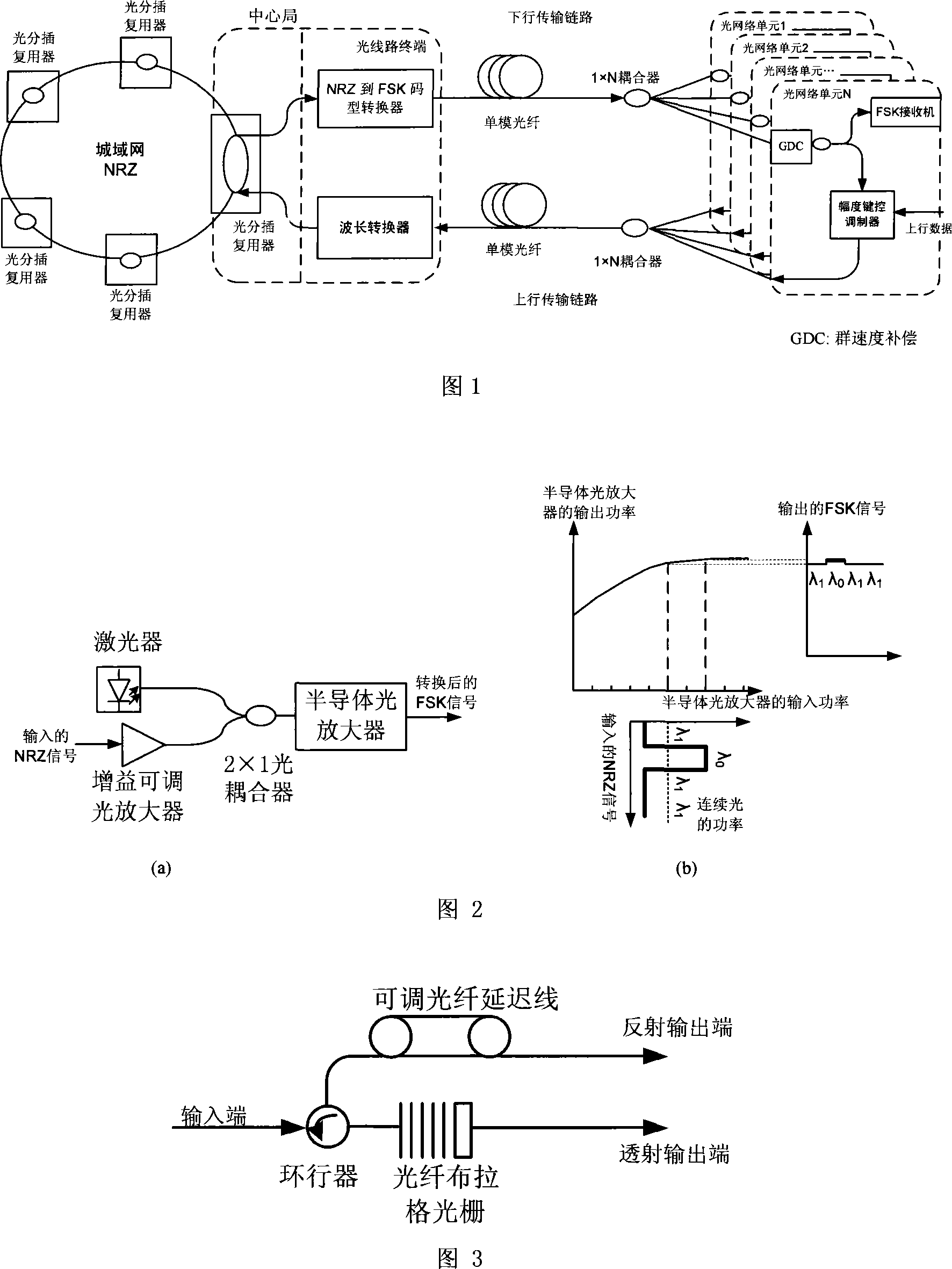
[0021] As shown in FIG. 1 , this embodiment includes: a central office, a downlink transmission link, an uplink transmission link, 1×N optical couplers and N optical network units. The central office includes an optical add-drop multiplexer and an optical line terminal; the central office is connected to the metropolitan area network through an optical add-drop multiplexer, and connected to the passive optical network through an optical line terminal; the optical line terminal is connected to each optical line terminal The network units are connected by uplink and dow...


PUM


Abstract

The invention relates to an all optical network interconnection system of a passive optical network and a metropolitan area network which belong to the technical field of optical fiber communications, and the system includes a center bureau, a downlink transmission link, an uplink transmission link, 1*N optical coupler and N corresponding optical network units, wherein, the center bureau consists of an optical add-drop multiplexer and an optical line terminal, and the center bureau is connected with the metropolitan area network via the optical add-drop multiplexer and is accessed into the passive optical network; the optical line terminal is connected with the 1*N optical coupler via an optical fiber, and the output end of the 1*N optical coupler is connected with the N optical network units to form the downlink transmission link; the N optical network units are connected with another optical fiber of the same length via another likewise 1*N optical coupler to form the uplink transmission link, and the uplink data is transmitted to the optical line terminal. The invention does not need electro-optic or optical-electrical conversion, and the optical network units do not need the light source, thereby greatly saving the cost of the passive optical network, and the utility model can be connected with more optical network units.

Description

technical field [0001] The invention relates to a system in the technical field of optical fiber communication, in particular to an all-optical network interconnection system of a passive optical network and a metropolitan area network. Background technique [0002] The existing optical network can be divided into three types according to the transmission distance: backbone network, metropolitan area network and access network. The access network directly provides services to users. A large amount of information needs to be exchanged between the land network of the city and the access network. Therefore, it has become necessary to realize the interconnection between the land network of the city and the access network without bottlenecks of all optics. Utilizing the existing low-cost optical devices, the passive optical network (PON) has become an attractive solution for users to realize broadband access network because of its simple structure and low cost. Traditionally, i...

Claims


Application Information

Patent Timeline
Patent Type & Authority Applications(China)
IPC IPC(8): H04B10/12H04B10/20H04Q11/00H04B10/27
Inventor 卢媛媛苏翼凯
Owner SHANGHAI JIAO TONG UNIV
Learn More