Reconfigurable multi-zoned fiber optic network architecture having fiber optic devices

a fiber optic network and multi-zone technology, applied in the field of fiber optic devices, can solve the problems of increasing installation time, cost and maintenance, and the complexity of fiber optic networks, and achieve the effect of reducing cost and labor

Inactive Publication Date: 2011-12-01
CORNING OPTICAL COMM LLC
View PDF5 Cites 56 Cited by
  • Summary
  • Abstract
  • Description
  • Claims
  • Application Information

AI Technical Summary

Benefits of technology

In this way, the service provider can initially configure the zone for the current number of subscribers, for example single family units, to be connected to the fiber optic network. As an example, this may be 30% of the subscribers, referred to as a 30% take rate. The service provider can defer the cost for the rest of the current and / or future subscribers. Only at the time the demand for optical communication service changes, for example increasing to a 50% or higher take rate level, does the service provider incur the cost to reconfigure the zone to meet that 50% or higher take rate. Additionally, the reconfiguration may be done at minimal cost and labor, particularly since the optical components and hardware may employ plug and play connections.

Problems solved by technology

To facilitate this capacity and reach, the fiber optic networks must employ additional fiber optic cable, hardware and components resulting in increased installation time, cost and maintenance.
This results in the fiber optic networks becoming more complex, requiring architectures that allow for the most efficient delivery of fiber optic service to the subscriber.

Method used


Image

  • Reconfigurable multi-zoned fiber optic network architecture having fiber optic devices
  • Reconfigurable multi-zoned fiber optic network architecture having fiber optic devices
  • Reconfigurable multi-zoned fiber optic network architecture having fiber optic devices

Examples


Embodiment Construction

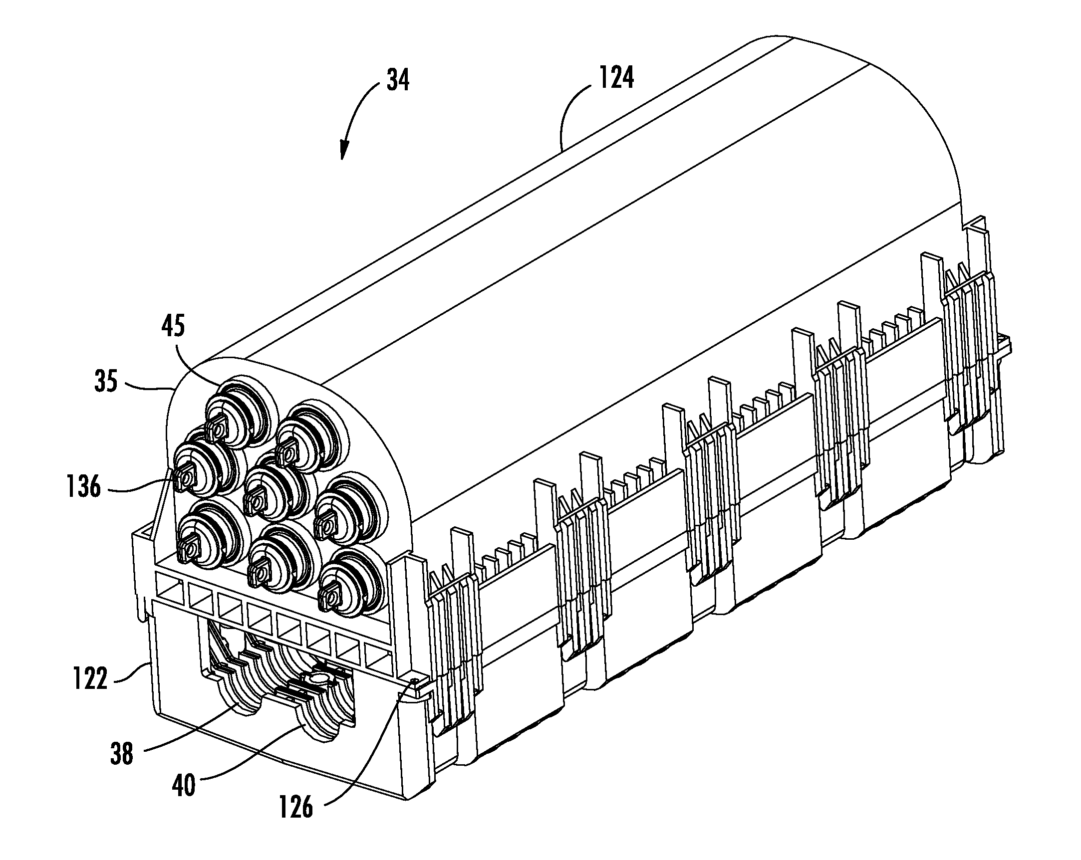
Embodiments disclosed in the detailed description include a fiber optic terminal, comprising an enclosure having a wall defining an interior cavity and a plurality of connector ports disposed through the wall. At least one adapter positions within one of the plurality of connector ports. The at least one adapter has an interior end accessible from within the interior cavity and an exterior end accessible external to the enclosure. The adapter is configured to establish an optical connection between at least one optical fiber attached to a first multi-fiber optical connector inserted in the interior end, and one or more respective optical fibers in a second multi-fiber optical connector inserted in the exterior end. The one or more respective optical fibers are optically connected to one or more optical fibers of a distribution cable. The second multi-fiber optical connector may be suitable for outside-plant installation. The terminal is configured to extend optical service from a se...


PUM


Abstract

A fiber optic network having one or more zones is disclosed. Each zone of the fiber optic network includes one or more zone terminals or devices. Such zone terminals or devices may be located at a mid-span access point of a distribution cable optically connected to a service provider's feeder cable. The zone terminal has a plurality of connector ports with at least one adapter positioned within one of the plurality of connector ports. The adapter is configured to establish an optical connection with one or more optical fibers of the distribution cable. The second multi-fiber optical connector is suitable for outside-plant installation, and the terminal is configured to extend optical service from a service provider toward at least one subscriber premises in a zone. The fiber optic terminal is reconfigurable based on at least one of, a number of subscriber premises in the zone, a geographical relationship of the subscriber premises in the zone, and a demographic make-up of the subscriber premises in the zone.

Description

BACKGROUND1. Technical FieldThe present invention relates generally to fiber optic devices, and more particularly to fiber optic devices arranged in multi-zoned distribution network architectures, which may be reconfigured to meet optical communication service requirements.2. Technical BackgroundOptical fiber is increasingly being used for a variety of broadband applications including voice, video and data transmissions. As a result of the ever-increasing demand for broadband communications, telecommunication and cable media, service providers and / or operators are expanding their fiber optic networks to increase their networks' capacity and reach to provide more services, applications and information to more subscribers. To facilitate this capacity and reach, the fiber optic networks must employ additional fiber optic cable, hardware and components resulting in increased installation time, cost and maintenance. This results in the fiber optic networks becoming more complex, requirin...

Claims


Application Information

Patent Timeline
Patent Type & Authority Applications(United States)
IPC IPC(8): H04J14/00
CPCH04J14/0282G02B6/445
Inventor BRADEA, DANIEL AURELBALLHAUSSEN, PETER CHARLES
Owner CORNING OPTICAL COMM LLC
Why Eureka
Try Eureka