This helps you quickly interpret patents by identifying the three key elements:
Problems solved by technology
Method used
Benefits of technology
Benefits of technology
[0013]According to the road configuration estimation apparatus of the present invention, the approximate curve is computed based on a result of the determination by the stationary object determination unit and a result of the determination by the object correlation unit. Thus, influences of erroneous detection and erroneous determination may be precluded, and reliability of the computed approximate curve may be thereby enhanced.
Problems solved by technology
When accuracy of distinction is low, the moving object may be erroneously determined to be the stationary object.
Method used
Image
Click on the blue label to locate the original text in one second.
Reading with bidirectional positioning of images and text.
Examples
first embodiment
[0073]A first embodiment will be described, using FIGS. 1 to 13.
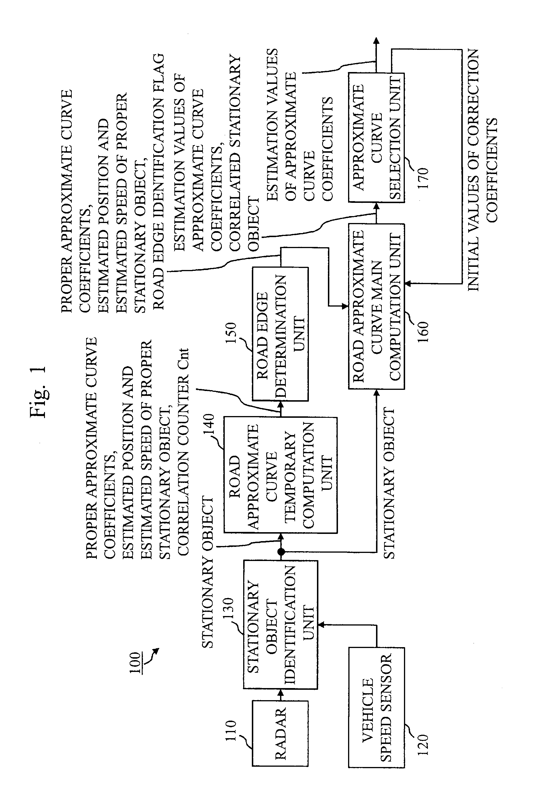
[0074]FIG. 1 is a block diagram showing a configuration of a road configuration recognition apparatus 100 in this embodiment.
[0075]The road configuration recognition apparatus 100 includes radar 110, a vehicle speed sensor 120, a stationary object identification unit 130, a road approximate curve temporary computation unit 140, a road edge determination unit 150, a road approximate curve main computation unit 160, and an approximate curve selection unit 170.
[0076]The radar 110 (peripheral object observation device) radiates a radar wave within a predetermined angle range ahead of a vehicle, and receives a radar wave reflected from an object, thereby detecting the position and relative speed of the object.
[0077]The vehicle speed sensor 120 (moving speed observation device) detects the speed of the vehicle.
[0078]The stationary object identification unit (stationary object determination unit) 130 identifies whether or not ...
second embodiment
[0141]A second embodiment will be described using FIG. 14.
[0142]Same reference numerals are assigned to components common to those in the first embodiment, thereby omitting repeated description of the components.
[0143]FIG. 14 is a block diagram showing a configuration of a road approximate curve temporary computation unit 140 in this embodiment.
[0144]The road approximate curve temporary computation unit 140 includes a stationary object clustering unit 141, in addition to the configuration described in the first embodiment.
[0145]The road approximate curve temporary computation unit 140 performs clustering of stationary objects, and tracks a cluster.
[0146]Next, operation will be described.
[0147]Under an actual road running environment, there is reflection from a stationary object such as a delineator, a guardrail or a wall. A plurality of reflection points are obtained from the stationary object having a large surface area such as the guardrail or the wall in particular. Thus, it may ...
third embodiment
[0149]A third embodiment will be described using FIGS. 15 to 16.
[0150]The same reference numerals are assigned to components common to those in the first and second embodiments, thereby omitting repeated description of the components.
[0151]FIG. 15 is a block diagram showing a configuration of an approximate curve selection unit 170 in this embodiment.
[0152]The approximate curve selection unit 170 includes a smoothing unit 175 and a coefficient estimation value accumulation unit 176, in addition to the configuration described in the first embodiment.
[0153]The approximate curve selection unit 170 smoothes approximate curve coefficients using the inclination of an approximate curve at an immediately preceding time and the inclination of an approximate curve selected at a current time.
[0154]Next, operation will be described.
[0155]FIG. 16 is an explanatory diagram for explaining a problem encountered when an approximate curve is selected.
[0156]When the inclination of an approximate curve...
PUM
Abstract
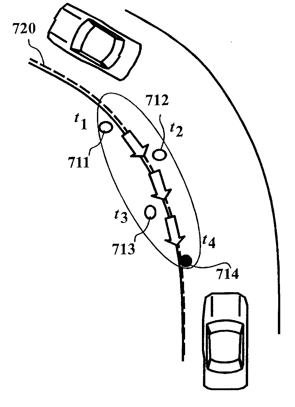
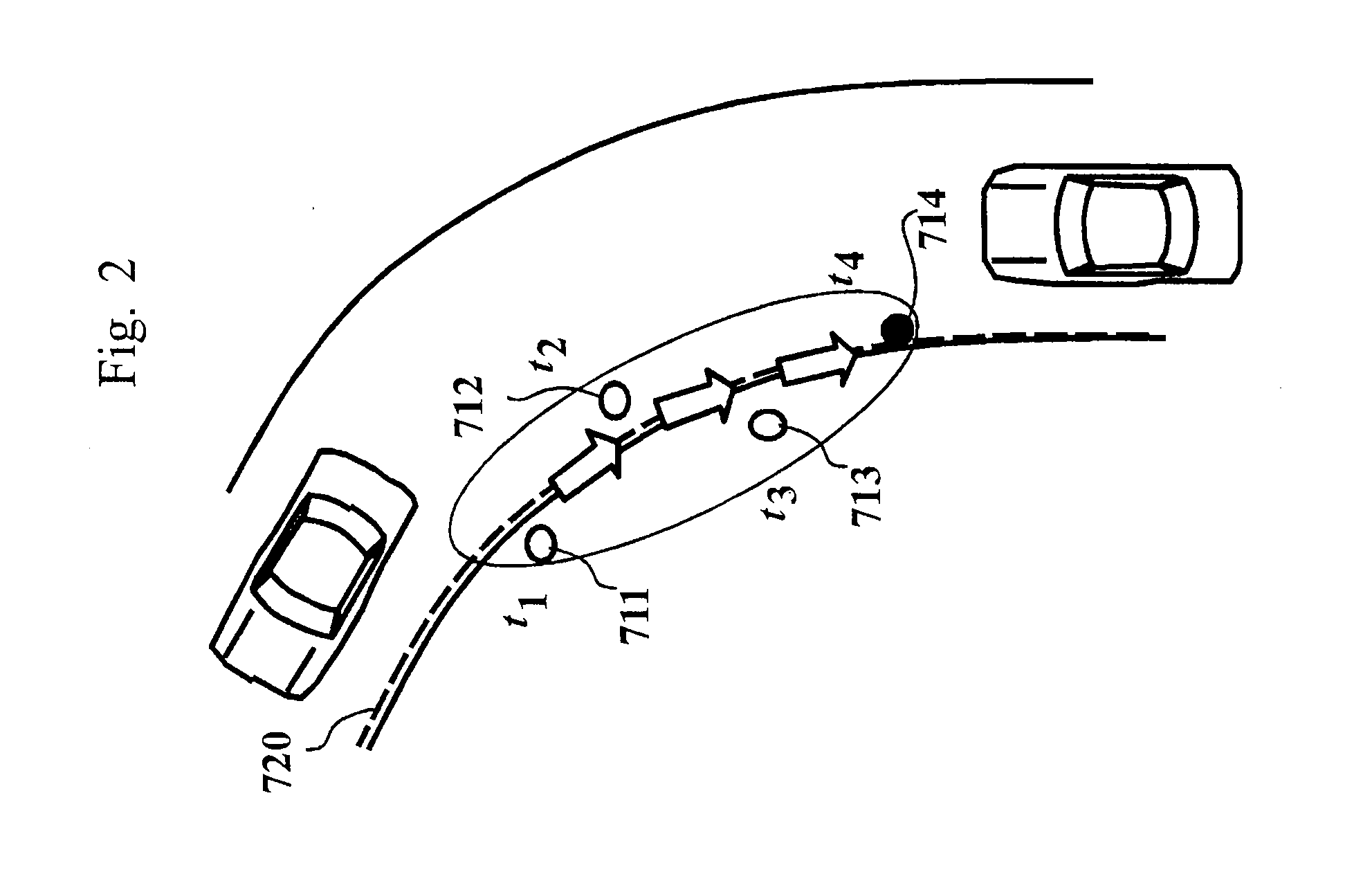
There is provided a road configuration estimation apparatus that precludes influences of erroneous detection of an object and erroneous still determination and estimates a road configuration.A radar (peripheral object observation device) 110 repeatedly observes a relative position of an object relative to the moving object, which is located in the vicinity of a moving object. A stationary object identification unit (stationary object determination unit) 130 determines whether or not the object the relative positions of which have been observed by the radar 110 is still. A road approximate curve temporary computation unit (object correlation unit) 140 determines a plurality of the relative positions of an identical object observed by the radar 110 from among the relative positions observed by the radar 110. A road approximate curve main computation unit (approximate curve computation unit) 160 computes an approximate curve that approximates the configuration of a road on which the moving object is located, based on a result of the determination by the stationary object identification unit 130 and a result of the determination by the road approximate curve computation unit 140.
Description
TECHNICAL FIELD[0001]The present invention relates to a road configuration estimation apparatus that estimates a configuration of a road on which a moving object is located.BACKGROUND ART[0002]There is provided a device that estimates a configuration of a road, based on a result of observation by a camera or radar that monitors a running direction of a moving object. While a stationary object such as a delineator or a guardrail is present at a road edge, no stationary object is present on the roadway of the road. For this reason, when the position of the stationary object is known, the configuration of the road may be estimated.RELATED ART DOCUMENTS[0003][Patent Document 1] JP Patent Application Publication JP-2001-250197A[0004][Patent Document 2] JP Patent Application Publication JP-2007-66047ASUMMARY OF INVENTION[0005]An observation device such as radar may observe an object that is not actually present due to an influence of noise, a multipath, or the like. Further, a moving obje...
Claims
Application Information
Patent Timeline
Application Date:The date an application was filed.
Publication Date:The date a patent or application was officially published.
First Publication Date:The earliest publication date of a patent with the same application number.
Issue Date:Publication date of the patent grant document.
PCT Entry Date:The Entry date of PCT National Phase.
Estimated Expiry Date:The statutory expiry date of a patent right according to the Patent Law, and it is the longest term of protection that the patent right can achieve without the termination of the patent right due to other reasons(Term extension factor has been taken into account ).
Invalid Date:Actual expiry date is based on effective date or publication date of legal transaction data of invalid patent.

