Ball screw apparatus and electric power steering apparatus

a technology of electric power steering and screw, which is applied in the direction of hoisting equipment, gearing, transportation and packaging, etc., can solve the problems of rapid increase in load, and easy clogging of balls by rapidly increasing load, and achieve high efficiency of transmitting torque

a technology of electric power steering and screw, which is applied in the direction of hoisting equipment, gearing, transportation and packaging, etc., can solve the problems of rapid increase in load, and easy clogging of balls by rapidly increasing load, and achieve high efficiency of transmitting torque

US20110296939A1Active Publication Date: 2011-12-08JTEKT CORP

Image

  • Ball screw apparatus and electric power steering apparatus
  • Ball screw apparatus and electric power steering apparatus
  • Ball screw apparatus and electric power steering apparatus

Examples


first embodiment

[0034 of a ball screw apparatus and an electric power steering apparatus according to the present invention will be described referred to FIG. 1 to FIG. 14.

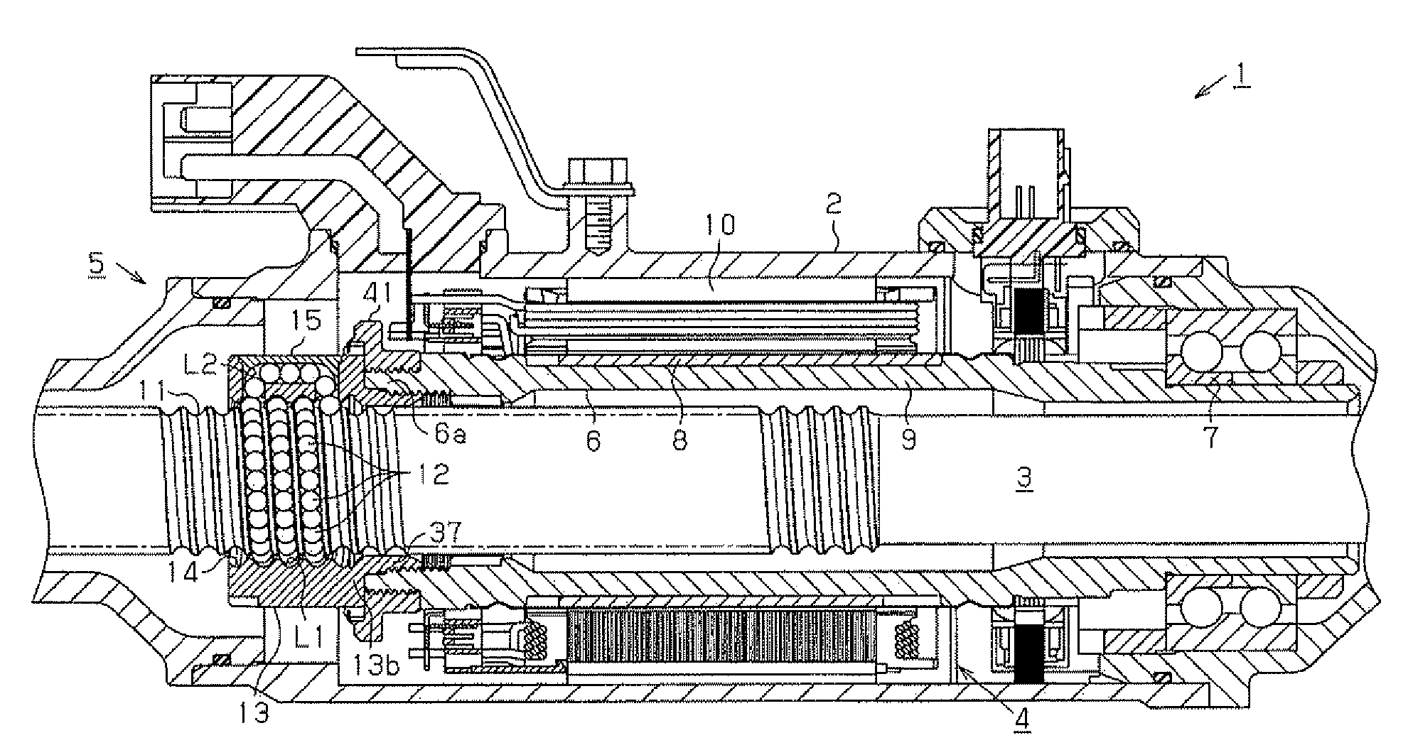
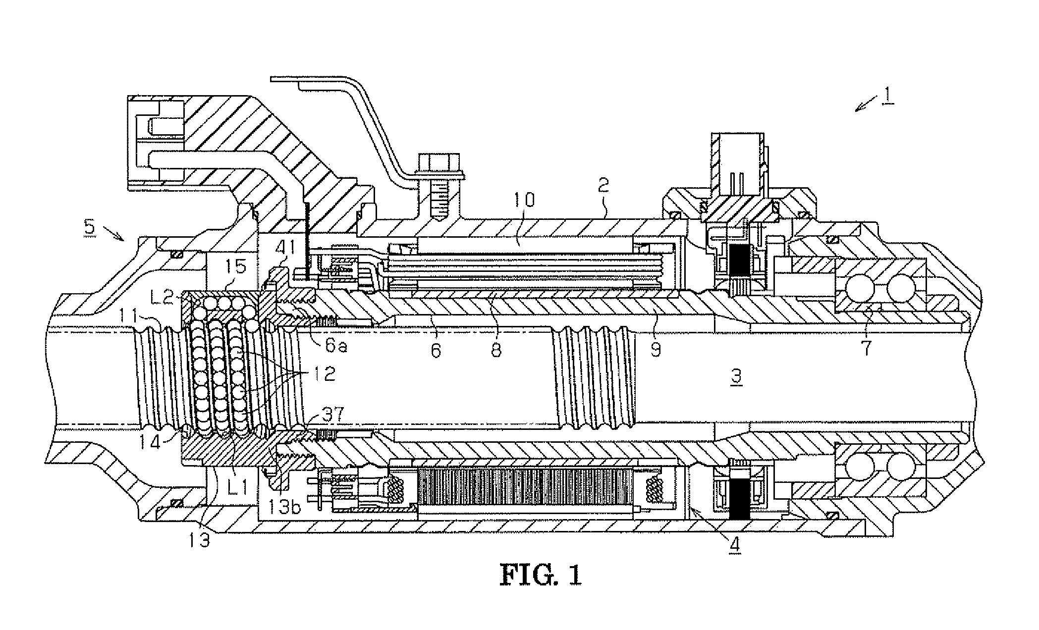
[0035]In an electric power steering apparatus 1 (referred to EPS hereinafter) shown in FIG. 1, a rack shaft 3 is penetrated through a housing 2 being approximately cylindrical, and accommodated and supported therein by an un-illustrated rack guide and an un-illustrated slide bearing for moving along an axis of the housing 2. The rack shaft 3 is movable according to operations of a steering wheel by being connected to a steering shaft through well-known rack and pinion mechanism. The EPS 1 includes a motor 4 as a driving source and a ball screw equipment 5 transmitting a rotational movement of the motor 4 by exchanging it to an axial movement of the rack shaft 3. The EPS 1 is constructed as the rack assisted EPS accommodating the rack shaft 3, the motor 4 and the ball screw equipment 5 as a function of a single body.

[0036]The moto...

second embodiment

[0068 of the present invention will be explained hereinafter referred to FIGS. Any constructions with same numerals in the second embodiment to that in the first embodiment will be omitted to be explained.

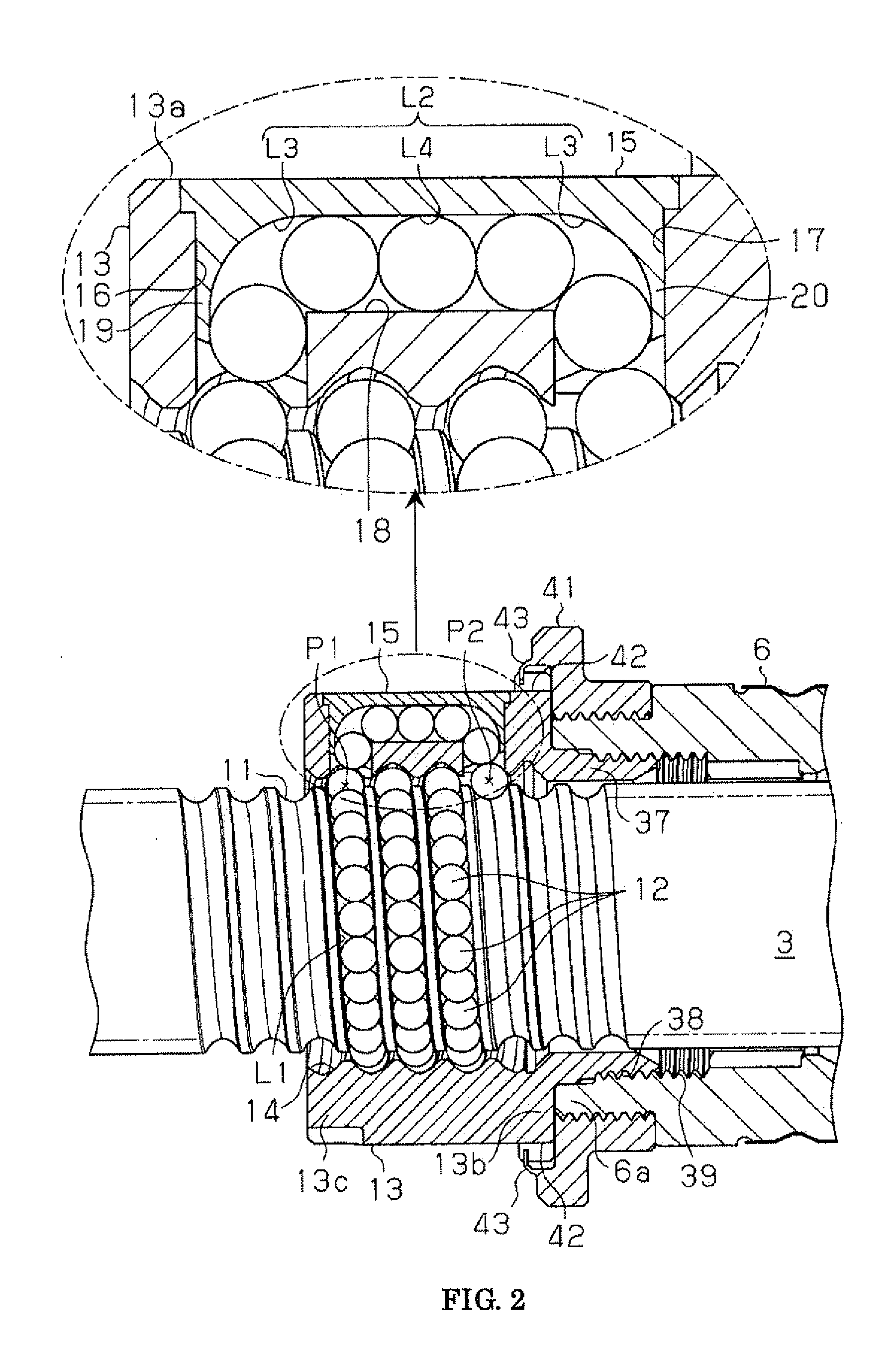
[0069]As shown in FIG. 15 the expanding portion 52 in the second embodiment includes the connecting area 34 in a way that a center O2 of the arc part that is offset to a direction of the circulating member 15 in relating to the shaft center O1 of the rack shaft 3. The connecting area 34 has the continuous arc part within one circle from the jointing point32, in the second embodiment within 45 degrees clockwise around the shaft center O1.

[0070]The expanding portion 52 includes a straight section 61 and a curved section 62. The straight section 61 extends along a tangential direction from the jointing area 53 of the base portion 51 and the expanding portion 52 in the nut side screw groove 14. The curved section 62 continues to the straight section 61 and includes the connecting area ...


PUM


Abstract

The ball screw apparatus includes a returning way L2 by mounting a circulating member 15 in mounted holes 16, 17 formed in the ball screw nut 13. The ball screw nut 13 includes a base portion 51 and an expanding portion 52. In the base portion 50 a distance from an axis center O1 of the rack shaft 3 to a bottom portion 14a of the nut side screw groove 14 is constant, and in the expanding portion 52 the distance is larger than that of the base portion 51. The expanding portion 52 includes a connecting area 34.

Description

INCORPORATION BY REFERENCE[0001]The disclosure of Japanese Patent Application No. 2010-129947 filed on Jun. 7, 2010 including the specification, drawings and abstract, is incorporated herein by reference in its entirety.BACKGROUND OF THE INVENTOIN[0002]1. Field of the Invention[0003]The present invention relates to a ball screw apparatus and an electric power steering apparatus.[0004]2. Description of the Related Art[0005]It is well known that there is a rack assisted electric power steering apparatus (EPS) having a hollow cylindrical shaft penetrated by a rack shaft and rotatably driven by a motor to transform rotational movement of the hollow cylindrical shaft to axial movement of the rack shaft by a ball screw apparatus, therefore assisting rotation of a steering wheel.[0006]The conventional ball screw apparatus of the EPS includes a plurality of balls rotating in a spiral rotating way formed by facing a nut side screw groove formed on an inner peripheral surface the ball screw n...

Claims


Application Information

Patent Timeline
08 Dec 2011
Publication
US20110296939A1
IPC
F16H25/22
CPC
F16H25/2214; Y10T74/19753; Y10T74/19767; Y10T74/19772; B62D5/0448
Inventors
KANEKO, TETSUYA; ASAKURA, MASAYOSHI