Heat-conducting module and heat-dissipating device having the same

a heat dissipating device and heat-conducting module technology, applied in semiconductor devices, semiconductor/solid-state device details, lighting and heating apparatus, etc., can solve the problems of large amount of heat generated during the operation of electronic elements, temperature rise of electronic elements, and affect the performance of electronic elements, so as to achieve the effect of increasing the heat-conducting

Inactive Publication Date: 2011-12-08
CELSIA TECH TAIWAN INC
View PDF0 Cites 23 Cited by
  • Summary
  • Abstract
  • Description
  • Claims
  • Application Information

AI Technical Summary

Benefits of technology

The heat-conducting module and heat-dissipating device described in this patent have a vapor chamber that increases the contact area between the vapor chamber and the heat pipe, thereby improving heat conduction. The vapor chamber has an evaporating section in thermal contact with the electronic heat-generating element and a heat-conducting section located away from the evaporating section and wrapping around the heat pipe. This wrapped heat-conducting section can increase the contact area between the vapor chamber and the heat pipe, allowing for faster heat dissipation to the outside. The heat-dissipating fin assembly connected to the heat-releasing section of the heat pipe can further enhance the heat dissipation process.

Problems solved by technology

The technical problem addressed in this patent is the need for effective heat-conducting members to prevent the accumulation of heat inside electronic elements, which can affect their performance and even cause damage. The patent discusses the use of vapor chambers and heat pipes, which are commonly used for this purpose, and proposes a solution to increase the contact surface area between them to improve heat-conducting efficiency. However, current solutions require a thicker vapor chamber, which does not conform to requirements for compact design. The present inventor aims to address this problem and improve the heat-conducting efficiency between the vapor chamber and heat pipe.

Method used


Image

  • Heat-conducting module and heat-dissipating device having the same
  • Heat-conducting module and heat-dissipating device having the same
  • Heat-conducting module and heat-dissipating device having the same

Examples


Embodiment Construction

The characteristics and technical contents of the present invention will be described with reference to the accompanying drawings. However, the drawings are illustrative only but not used to limit the present invention.

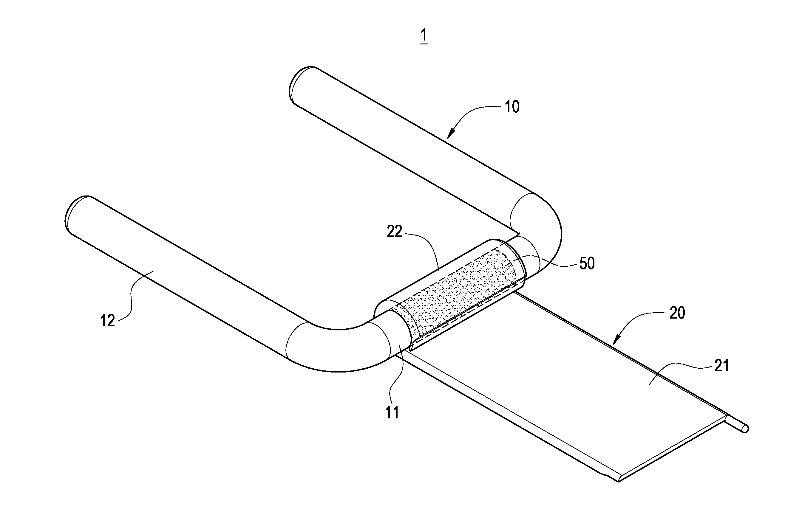
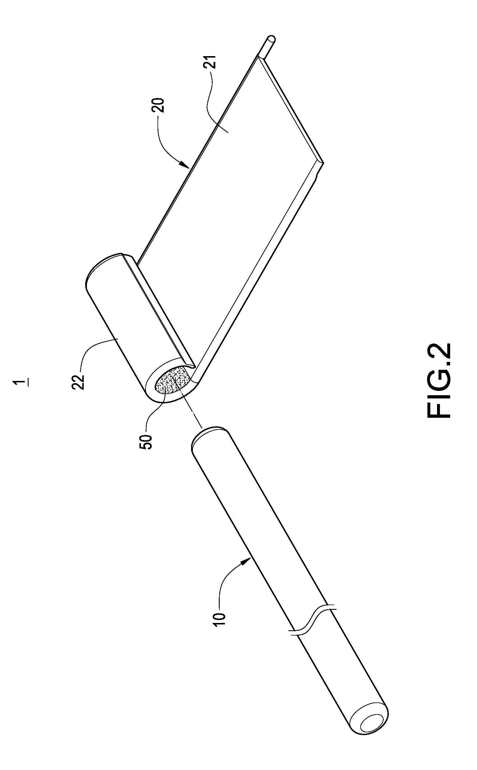
Please refer to FIGS. 1 to 6. The present invention provides a heat-conducting module 1 and a heat-dissipating device 2 having the heat-conducting module 1.

The heat-conducting module 1 of the present invention includes a heat pipe 10 and a vapor chamber 20. The heat-dissipating device 2 includes the heat pipe 10, the vapor chamber 20, a heat-dissipating fin assembly 30 and a fan 40. Since the internal structures of the heat pipe 10 and the vapor chamber 20 are well-known and not the characteristics of the present invention, the description relating thereto is omitted for clarity.

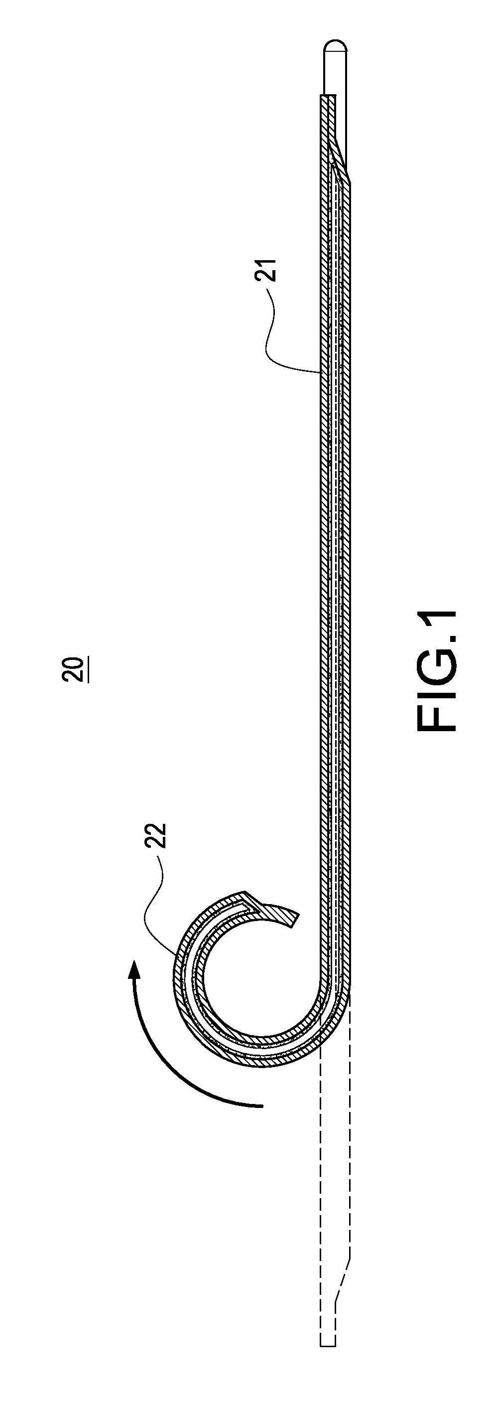
As shown in FIG. 1, the vapor chamber 20 has an evaporating section 21 adhered to an electronic heat-generating element (not shown) and a heat-conducting section 22 located away from the evapo...


PUM


Abstract

A heat-conducting module for heat conduction of an electronic heat-generating element includes a heat pipe and a vapor chamber. The vapor chamber has an evaporating section brought into thermal contact with the electronic heat-generating element and a heat-conducting section located away from the evaporating section and wrapping around the heat pipe. With this arrangement, the contact area and heat-conducting efficiency between the vapor chamber and the heat pipe can be increased greatly, thereby obtaining a heat-conducting module with an excellent heat-conducting efficiency. With a heat-dissipating fin assembly and a fan being connected to the heat pipe, a heat-dissipating device having the aforesaid heat-conducting module can be obtained, whereby the heat of the vapor chamber and the heat pipe can be rapidly dissipated to the outside.

Description


Claims


Application Information

Patent Timeline
Owner CELSIA TECH TAIWAN INC
Why Eureka
Try Eureka