
Sputtering Target And Method Of Fabrication

a technology of sputtering target and fabrication method, which is applied in the direction of diaphragm, metallic material coating process, disc wheel, etc., can solve the problems of inefficient conversion from circular ingot shape to rectangular shape, waste of materials, and high cost of tantalum material, and achieve strong crystallographic texture and strong (111) crystallographic texture

Active Publication Date: 2011-12-08
GLOBAL ADVANCED METALS USA
View PDF0 Cites 2 Cited by
  • Summary
  • Abstract
  • Description
  • Claims
  • Application Information

AI Technical Summary

Benefits of technology

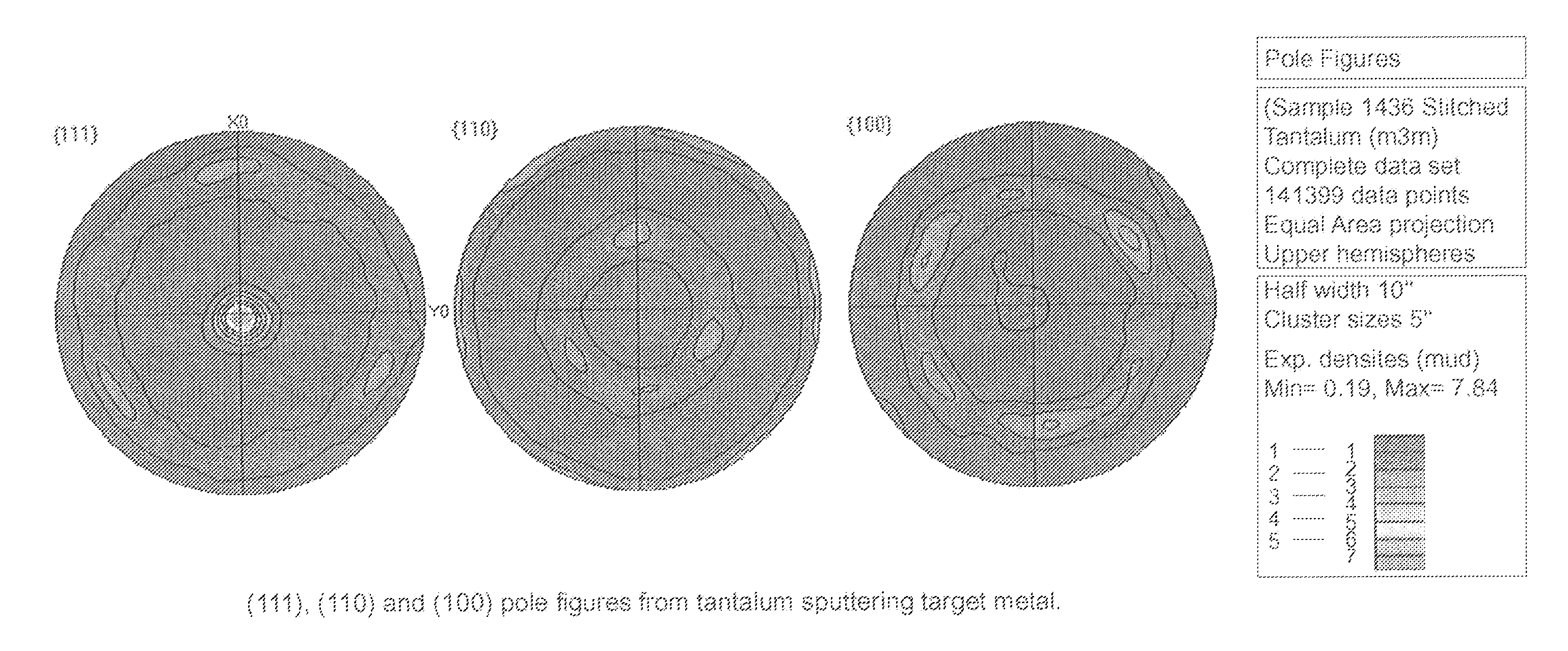
[0011]A further feature of the present invention is to provide a metal article, such as a sputtering target, which has very strong crystallographic texture, such as strong (111) crystallographic texture.

Problems solved by technology

This method can be very wasteful of expensive tantalum material.
This conversion from circular ingot shape to rectangular shape and back to circular shape is very inefficient and wasteful of material.

Method used


Image

  • Sputtering Target And Method Of Fabrication
  • Sputtering Target And Method Of Fabrication
  • Sputtering Target And Method Of Fabrication

Examples


examples

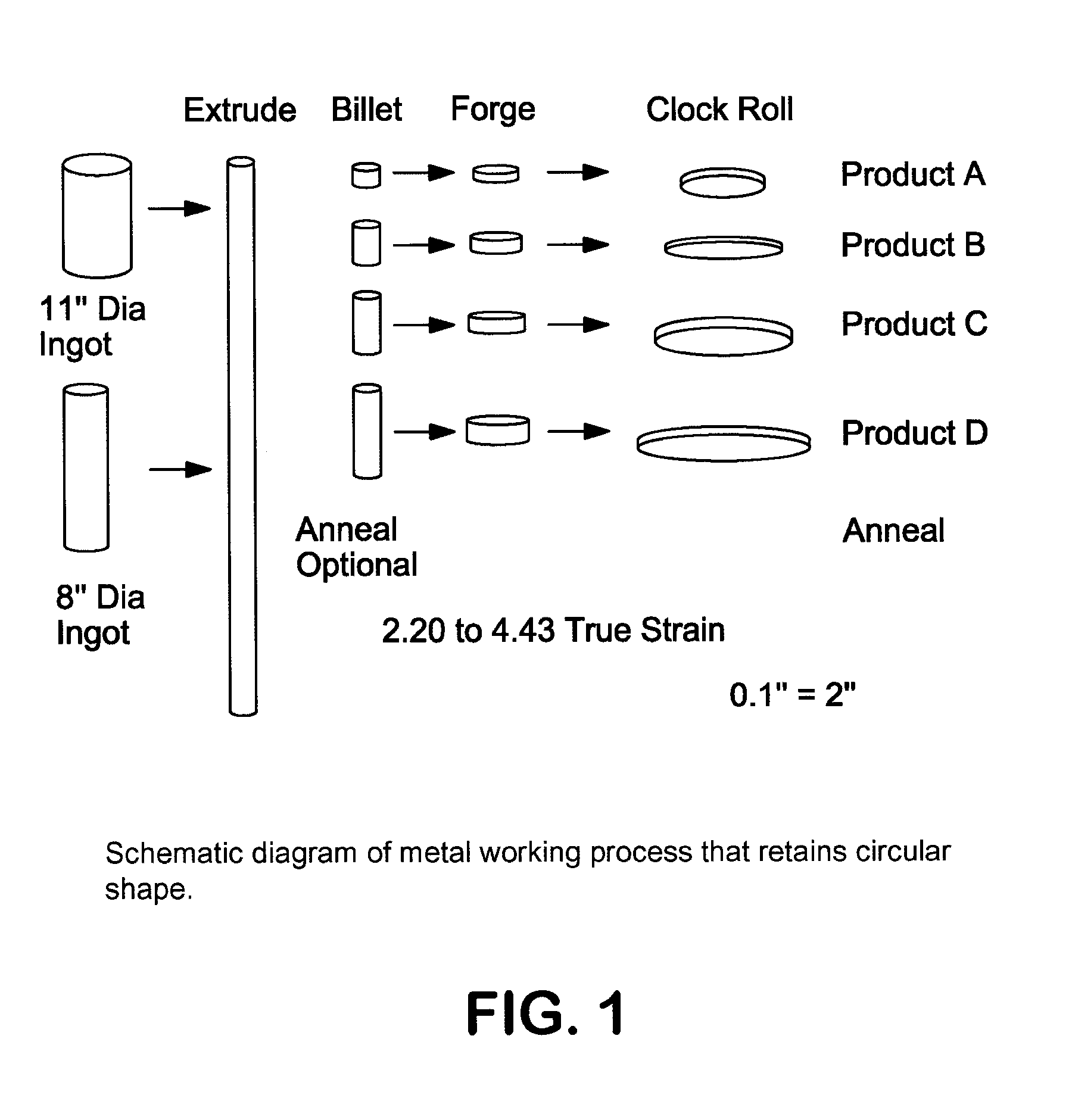
[0075]Several different products have been produced using the process of the present invention. The following examples are provided to illustrate how the product is produced.

[0076]Product A was produced by first swaging an 11 inch diameter tantalum ingot to a 5 inch diameter and then annealing the swaged ingot at 1050° C. for 2 hours. The annealed swaged ingot was then cut into a billet (3.24 inches tall). This billet was forged to a height of 1.26 inches. The forged billet was clock rolled using 9 to 27 passes in order to obtain a finish thickness of 0.36 inches. The rolled plate was annealed at 1050 C for 2 hours. Target disks produced in this way have a true strain prior to the final anneal of approximately 2.19 and have an average grain size of 30 μm and approximately 77% of their (111) planes aligned parallel to the plate surface. Disks produced in this example have a diameter of 15 inches.

[0077]An alternative method for producing product A is to not anneal after the swaging op...


PUM

PropertyMeasurementUnit
temperatureaaaaaaaaaa
temperaturesaaaaaaaaaa
lengthaaaaaaaaaa

Abstract

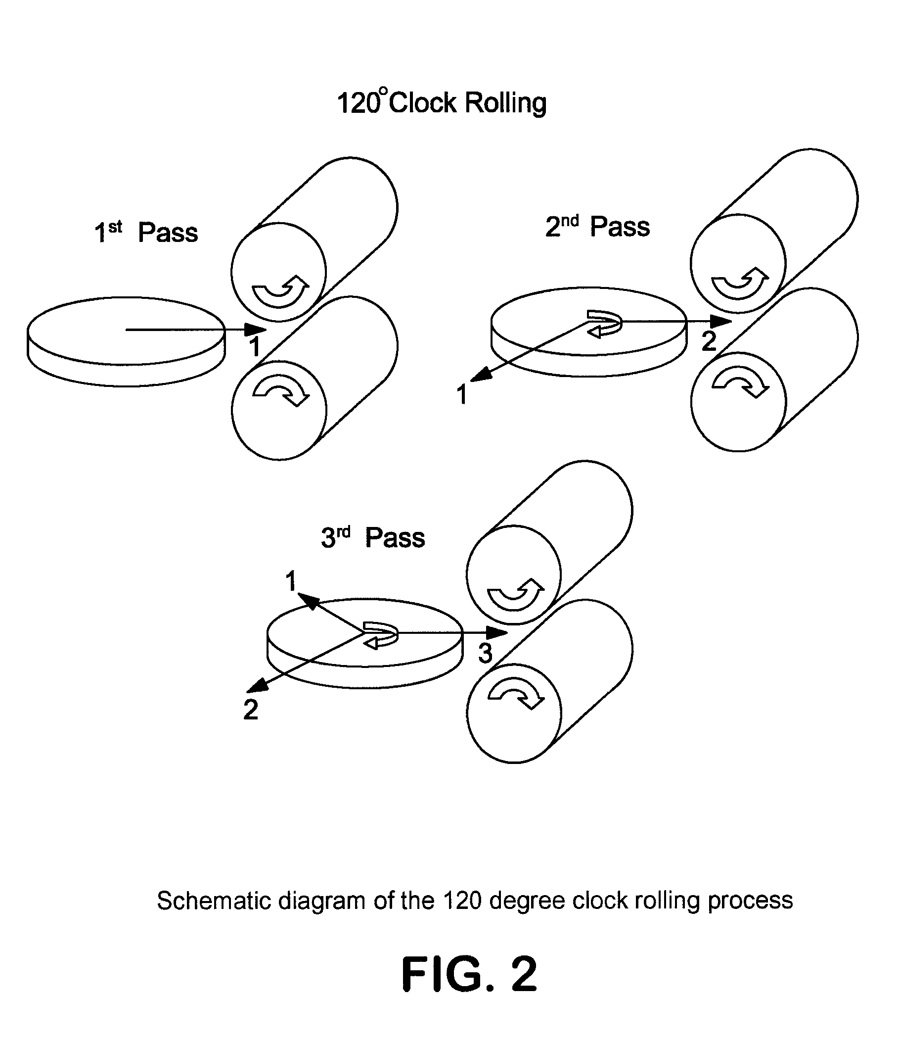
A process is described for processing metal which includes clock rolling a metal plate until the desired thickness is achieved to form a rolled plate. Sputtering targets and other metal articles are further described.

Description

BACKGROUND OF THE INVENTION[0001]The present invention relates to sputtering targets, such as tantalum and tantalum alloy-sputtering targets, and methods to make the same.[0002]In the sputter application field, a sputtering target assembly typically includes a sputter target and a backing plate. For instance, a metal target or metal target blank (e.g., tantalum, titanium, aluminum, copper, cobalt, tungsten, hafnium, and the like) is bonded onto a backing plate. The backing plate can be, for example, a backing plate flange assembly such as copper, aluminum, or alloys thereof. Among the factors that can affect sputtering performance of a given sputtering target assembly is the grain size and crystallographic orientation of the grains relative to the sputtering plane. The desired grain size and crystallographic texture are simultaneously achieved by using a combination of mechanical deformation and annealing.[0003]Previous methods for forming the desired metallurgical structure in tant...

Claims


Application Information

Patent Timeline
Patent Type & Authority Applications(United States)
IPC IPC(8): C23C14/34B32B3/02
CPCB21B1/02B21H1/02Y10T428/12243C22F1/18C23C14/3414C22C27/02C23C14/34B21B1/38
Inventor WICKERSHAM, JR., CHARLES E.LEVIT, VLADIMIRALEXANDER, P. TODD
Owner GLOBAL ADVANCED METALS USA
Learn More