

Tantalum sputtering target and method of fabrication
a technology of sputtering target and sputtering material, which is applied in the direction of transportation and packaging, vacuum evaporation coating, coating, etc., can solve the problems of wasteful method of tantalum material, waste of material, and inefficient conversion from circular ingot shape to rectangular shape and back to circular shape, etc., to achieve strong crystallographic texture and strong (111) crystallographic texture
- Summary
- Abstract
- Description
- Claims
- Application Information
AI Technical Summary
Benefits of technology
Problems solved by technology
Method used
Image

Examples
examples
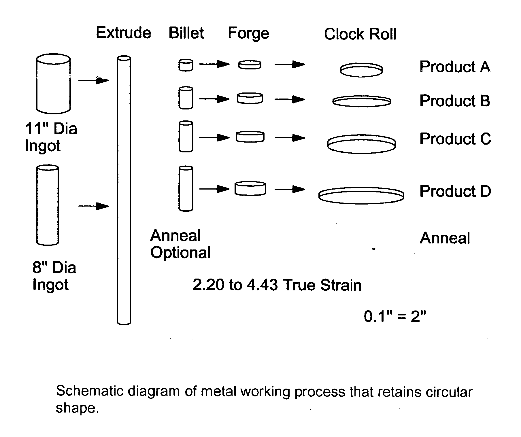
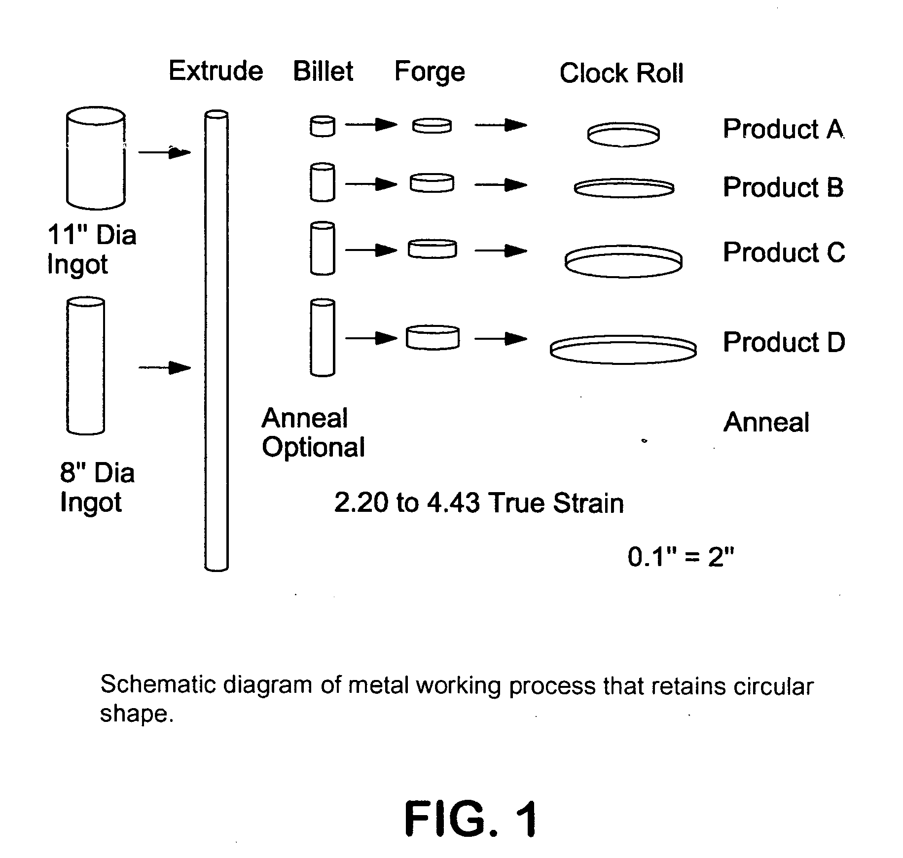
[0075] Several different products have been produced using the process of the present invention. The following examples are provided to illustrate how the product is produced.
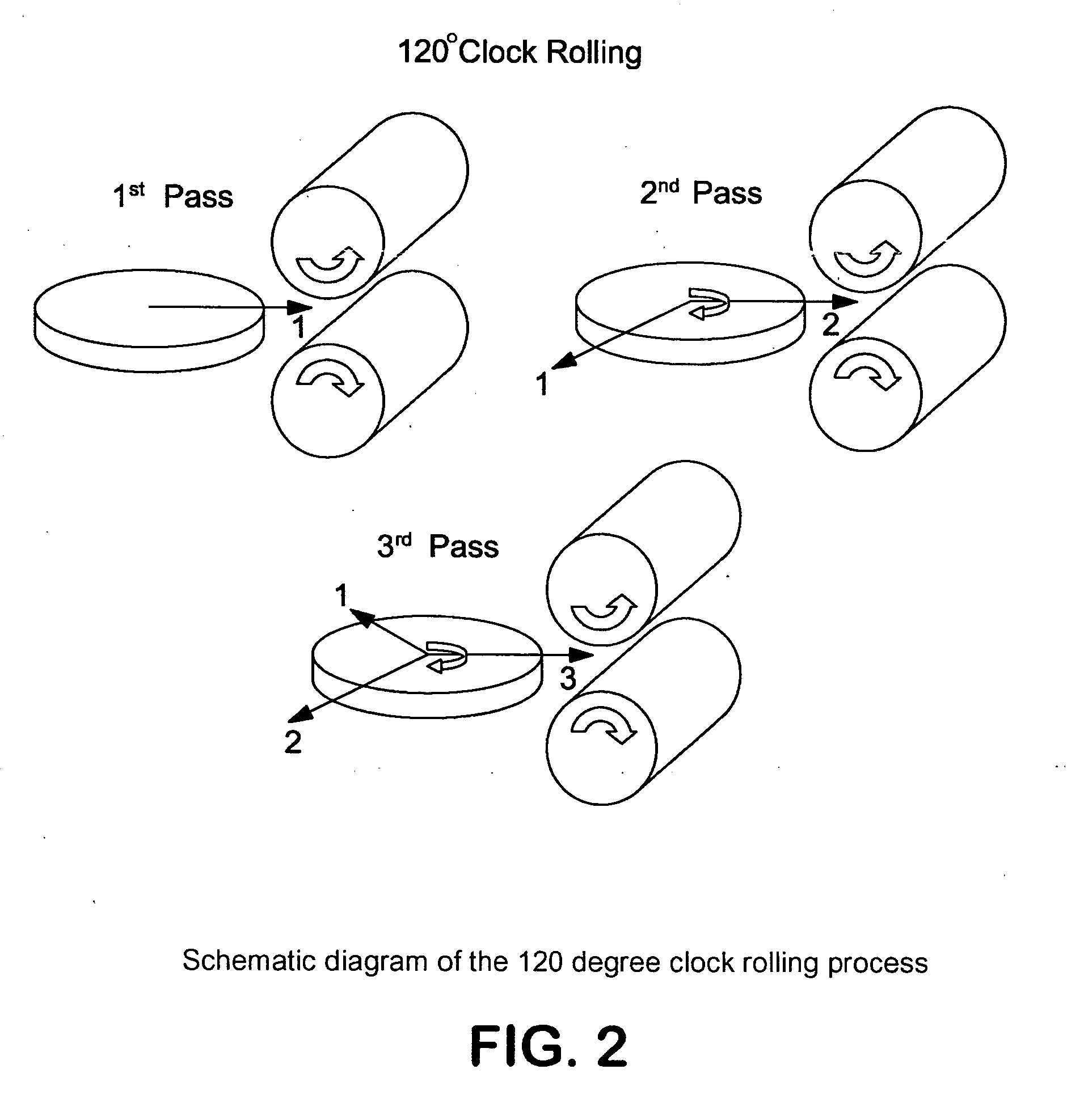
[0076] Product A was produced by first swaging an 11 inch diameter tantalum ingot to a 5 inch diameter and then annealing the swaged ingot at 1050° C. for 2 hours. The annealed swaged ingot was then cut into a billet (3.24 inches tall). This billet was forged to a height of 1.26 inches. The forged billet was clock rolled using 9 to 27 passes in order to obtain a finish thickness of 0.36 inches. The rolled plate was annealed at 1050 C for 2 hours. Target disks produced in this way have a true strain prior to the final anneal of approximately 2.19 and have an average grain size of 30 μm and approximately 77% of their (111) planes aligned parallel to the plate surface. Disks produced in this example have a diameter of 15 inches.
[0077] An alternative method for producing product A is to not anneal after the swagi...
PUM
| Property | Measurement | Unit |
|---|---|---|
| diameter | aaaaa | aaaaa |
| diameter | aaaaa | aaaaa |
| rotation | aaaaa | aaaaa |
Abstract
Description
Claims
Application Information