Display apparatus and display control method

a display apparatus and control method technology, applied in the field of display apparatus, can solve the problems of reducing the difficulty of completely reducing the transmittance of liquid crystal display elements to zero, and the problem described above is still unresolved, so as to improve the display quality of images

Inactive Publication Date: 2011-12-08
PANASONIC CORP
View PDF6 Cites 32 Cited by
  • Summary
  • Abstract
  • Description
  • Claims
  • Application Information

AI Technical Summary

Benefits of technology

The present invention is made to solve the problem described above, and an object of the present invention is to provide a display apparatus and a display control method capable of improving display quality of an image.
According to the present invention, the luminance control time required to reach the determined reference luminance value is determined for each of the image areas according to the detected moved amount. Thus, it is possible to prevent the brightened black by inhibiting rapid changes in luminance value of the illumination light in the case where the input image is a still image, and to change the luminance value of the illumination light according to the moved amount in the case where the input image is a moving image having a large moved amount, thereby making it possible to improve display quality of the image.

Problems solved by technology

However, it is difficult to completely reduce the transmittance of liquid crystal display elements to zero.
Since this unnatural movement of the brightened black portion is readily visible, display quality of the image decreases.
However, in Patent Document 1 as well, when the enlarged pixel area straddles a boundary between a plurality of divided areas, the same phenomenon as the problem described above occurs.
Consequently, the problem described above is still unresolved.
In addition, in the case where an object straddles a boundary between a plurality of divided areas, the brightness of the backlight changes suddenly and appears unnaturally in the form of a “halo” (the leaked light of the backlight from around the object).
Thus, there is also a problem of a decrease in display quality.
In this case, however, in a scene such that a flash from a camera and the like suddenly flashes, the luminance of the backlight for representing the light from the flash is unable to be secured adequately due to the effect of the LPF, thereby resulting in the problem of being unable to adequately represent the light from the flash.Patent Document 1: Japanese Patent Application Laid-open No. 2001-142409

Method used


Image

  • Display apparatus and display control method
  • Display apparatus and display control method
  • Display apparatus and display control method

Examples


first embodiment

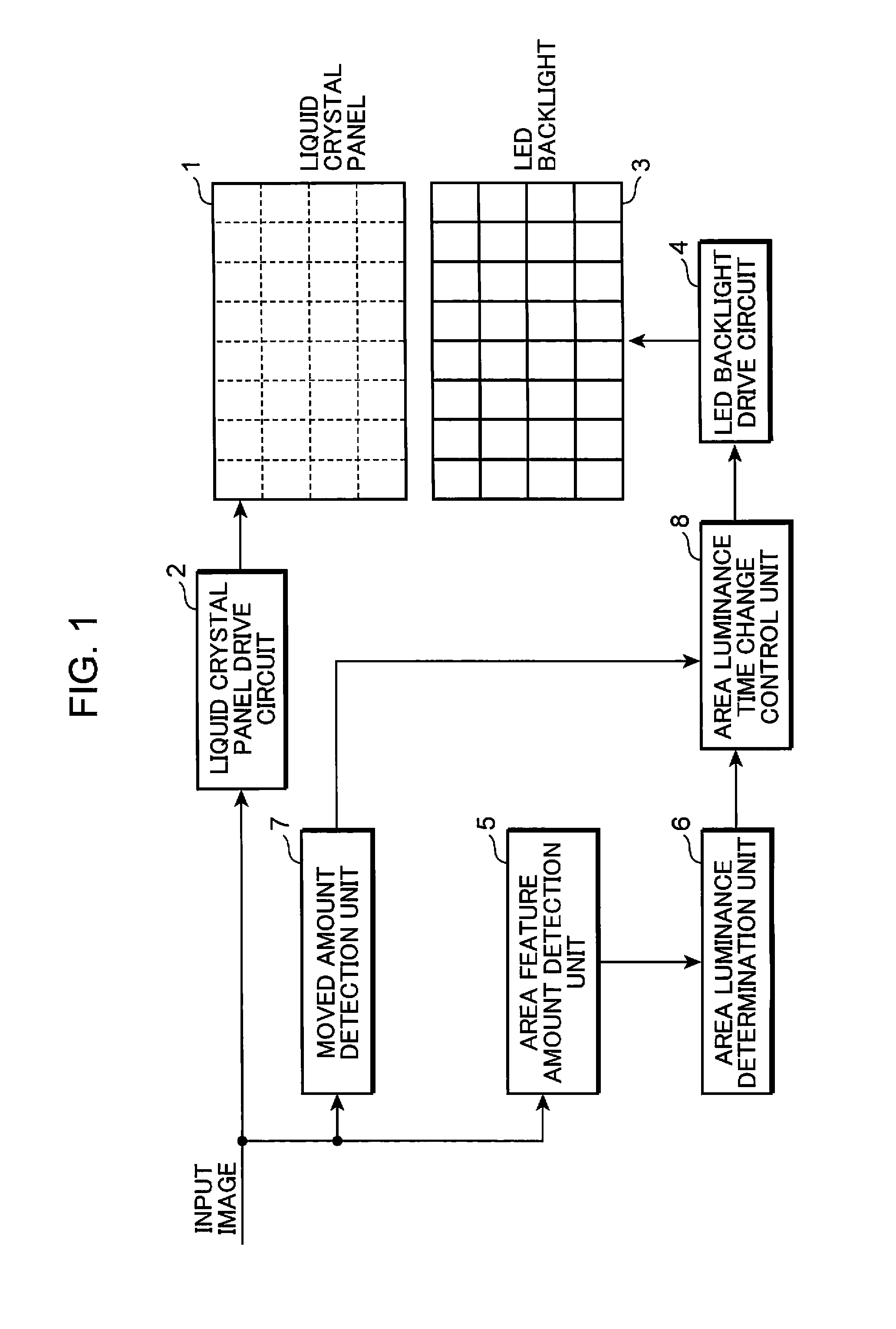
First, a description is provided of a liquid crystal display apparatus according to a first embodiment of the present invention. FIG. 1 is a block diagram showing the entire configuration of a liquid crystal display apparatus according to the first embodiment of the present invention. The liquid crystal display apparatus shown in FIG. 1 is provided with a liquid crystal panel 1, a liquid crystal panel drive circuit 2, an LED (Light Emitting Diode) backlight 3, an LED backlight drive circuit 4, an area feature amount detection unit 5, an area luminance determination unit 6, a moved amount detection unit 7, and an area luminance time change control unit 8.

Although not shown in the drawing, the liquid crystal panel 1 is provided with a plurality of gate lines, a plurality of source lines, switching elements and a plurality of pixel cells, a plurality of pixels are arranged in the form of a matrix at the intersections of the plurality of source lines and the plurality of gate lines, and...

second embodiment

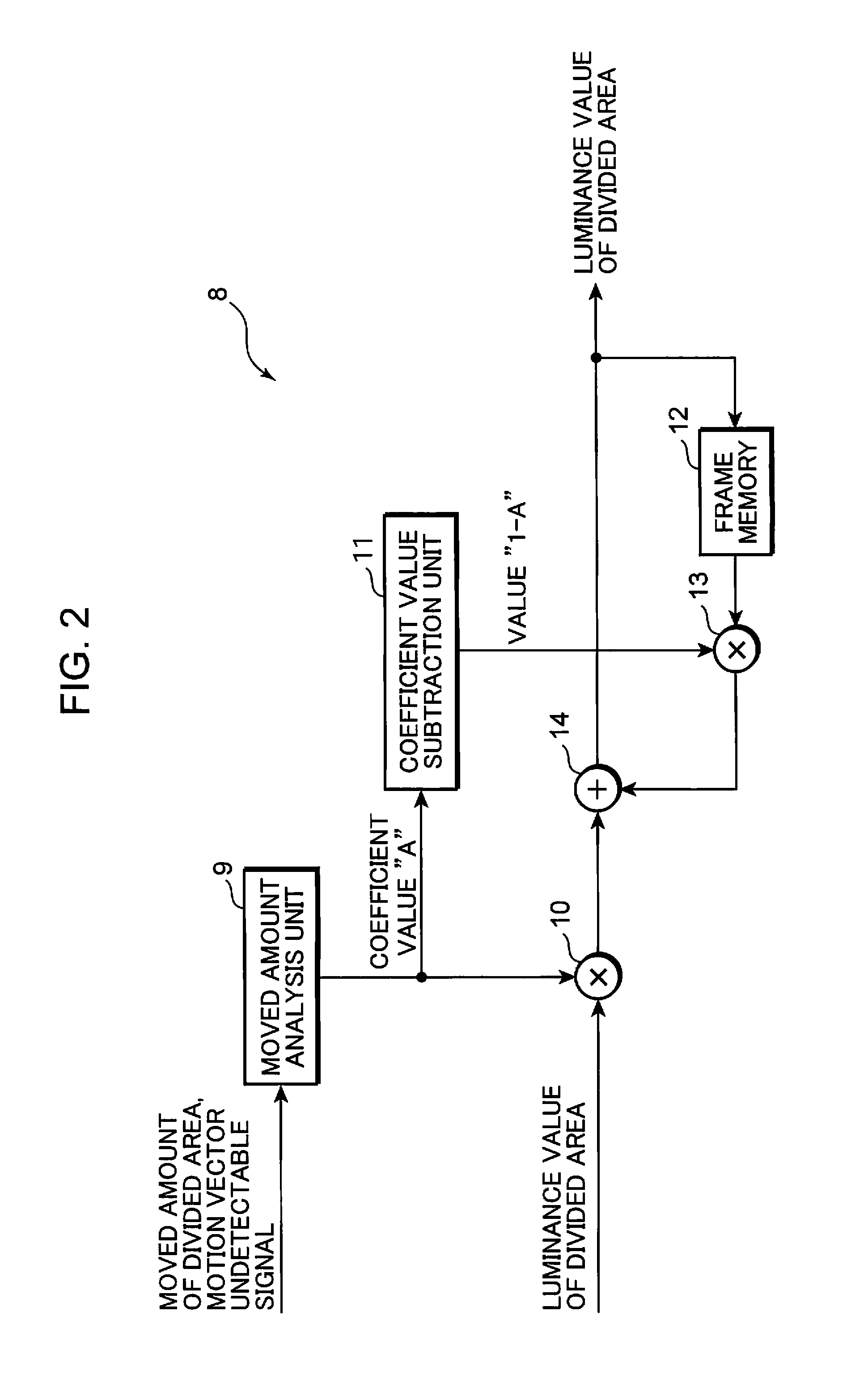
FIG. 15 is a block diagram showing a detailed configuration of the area luminance time change control unit 8 in a liquid crystal display apparatus of a second embodiment. Furthermore, a description of the entire configuration of the liquid crystal display apparatus of the second embodiment is omitted since it is the same as the liquid crystal display apparatus shown in FIG. 1. In addition, the same reference symbols are used in FIG. 15 to indicate those constituents that are the same as those of the area luminance time change control unit 8 shown in FIG. 2, and descriptions thereof are omitted.

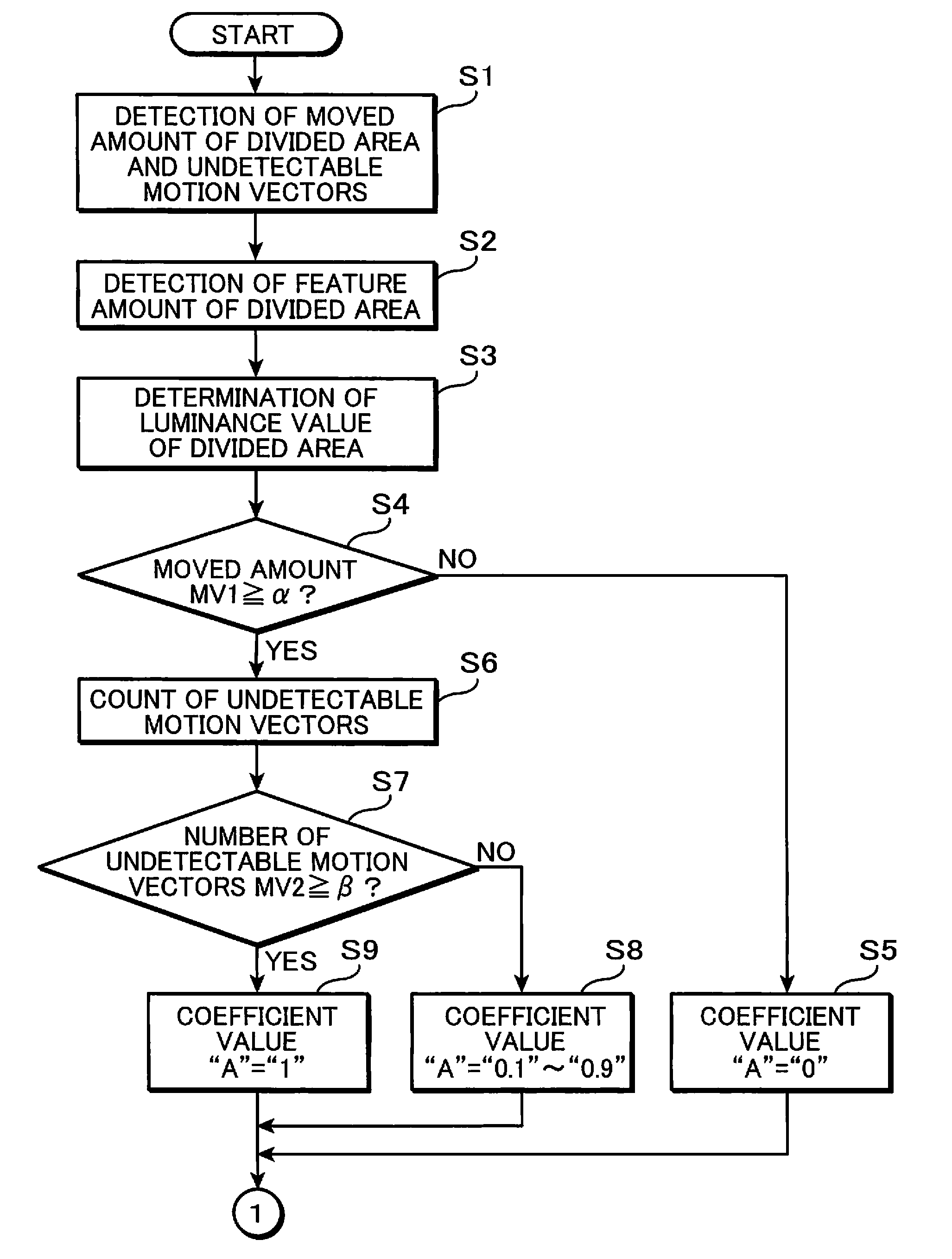
In the case where the moved amount detected by the moved amount detection unit 7 has been determined to be equal to or greater than a predetermined value, the area luminance time change control unit 8 shown in FIG. 15 counts the motion vectors in a divided area that cannot be detected by the moved amount detection unit 7 as undetectable motion vectors, and determines whether or not the number ...


PUM


Abstract

The present invention provides a display apparatus and a display control method capable of improving display quality of an image. The display apparatus is provided with an LED backlight (3) that illuminates each of a plurality of divided areas of a screen, a moved amount detection unit (7) that detects a moved amount of an input image in each of the divided areas, an area luminance determination unit (6) that determines a reference luminance value for each of the divided areas, an area luminance time change control unit (8) that determines a luminance control time required to reach the reference luminance value for each of the image areas, according to the moved amount, and an LED backlight drive circuit (4) that drives the LED backlight (3) based on the luminance control time for each of the image areas determined by the area luminance time change control unit (8).

Description

TECHNICAL FIELDThe present invention relates to a display apparatus that displays images by modulating irradiated light from an illumination light source with a light modulation element, and a display control method for controlling the illumination light source. More particularly, the present invention relates to a display apparatus and a display control method for controlling an illumination light source that illuminates each of a plurality of divided image areas of a screen.BACKGROUND ARTLiquid crystal display apparatuses, which use liquid crystal display elements (liquid crystal panel) as light modulation elements, are provided with an illumination light source on the back side thereof, and realize display of arbitrary images by controlling the transmittance of light irradiated from the illumination light source.Conventionally, liquid crystal display apparatuses control the luminance of a light source for each divided area obtained by dividing a display screen into a plurality of...

Claims


Application Information

Patent Timeline
Patent Type & Authority Applications(United States)
IPC IPC(8): G09G5/10
CPCG09G3/3426G09G2310/0237G09G2320/0238G09G2320/0247G09G2320/0261G09G2360/16G09G2320/0646G09G2320/0653G09G2320/106G09G2340/16G09G2320/064
Inventor NAKANISHI, ATSUSHI
Owner PANASONIC CORP
Why Eureka
Try Eureka