High NA Annular Field Catoptric Projection Optics using Zernike Polynomial Mirror Surfaces

a catoptric projection and polynomial mirror technology, applied in the field of high na annular field catoptric projection optics using zernike polynomial mirror surfaces, can solve the problems of design difficulty in manufacture, alignment, etc., and achieve the effect of large field

Active Publication Date: 2011-12-08
NIKON CORP
View PDF1 Cites 9 Cited by
  • Summary
  • Abstract
  • Description
  • Claims
  • Application Information

AI Technical Summary

Benefits of technology

[0005]The present invention provides optical components, optical structure, and design concepts that address the foregoing needs. The principles of the present invention can be used to design optical components, and optical structures, that can be used, e.g. to image at extreme ultraviolet (EUV) wavelengths, at a relatively high NA (e.g. 0.35), with a relatively large field of view (e.g. 26×2 mm). Moreover, an optical structure produced according to the principles of the present invention has a small amount of asymmetry, which enables the components of the optical structure to be manufactured with current manufacturing techniques.

Problems solved by technology

This makes such designs difficult to manufacture, as well as to align.h.

Method used


Image

  • High NA Annular Field Catoptric Projection Optics using Zernike Polynomial Mirror Surfaces
  • High NA Annular Field Catoptric Projection Optics using Zernike Polynomial Mirror Surfaces
  • High NA Annular Field Catoptric Projection Optics using Zernike Polynomial Mirror Surfaces

Examples


Embodiment Construction

[0025]As set forth above, the present invention provides optical components, optical structures, and an optical structure design method, that are particularly useful in producing optical structure for an imaging optical system such as a lithographic imaging optical system. The principles of the present invention are described herein in connection with a preferred design of an optical structure for a micro lithographic imaging optical system. However, from the description, the manner in which the principles of the present invention can be used in producing optical structure and optical components for various other types of optical systems will become apparent to those in the art.

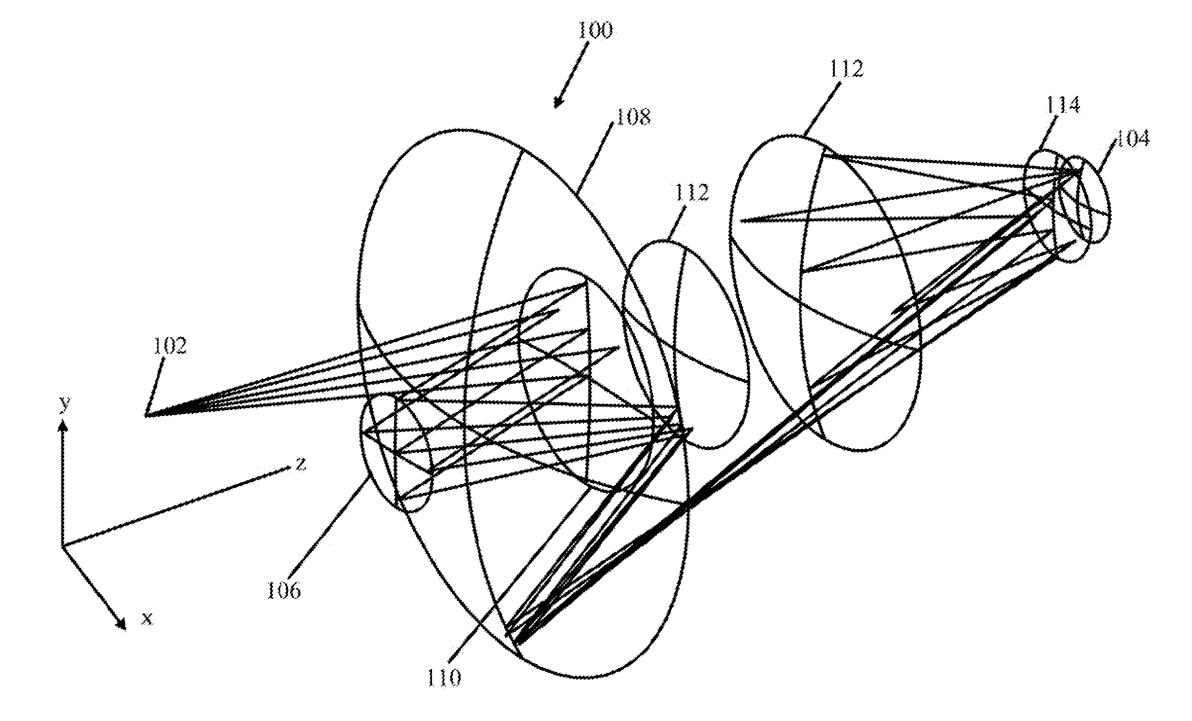
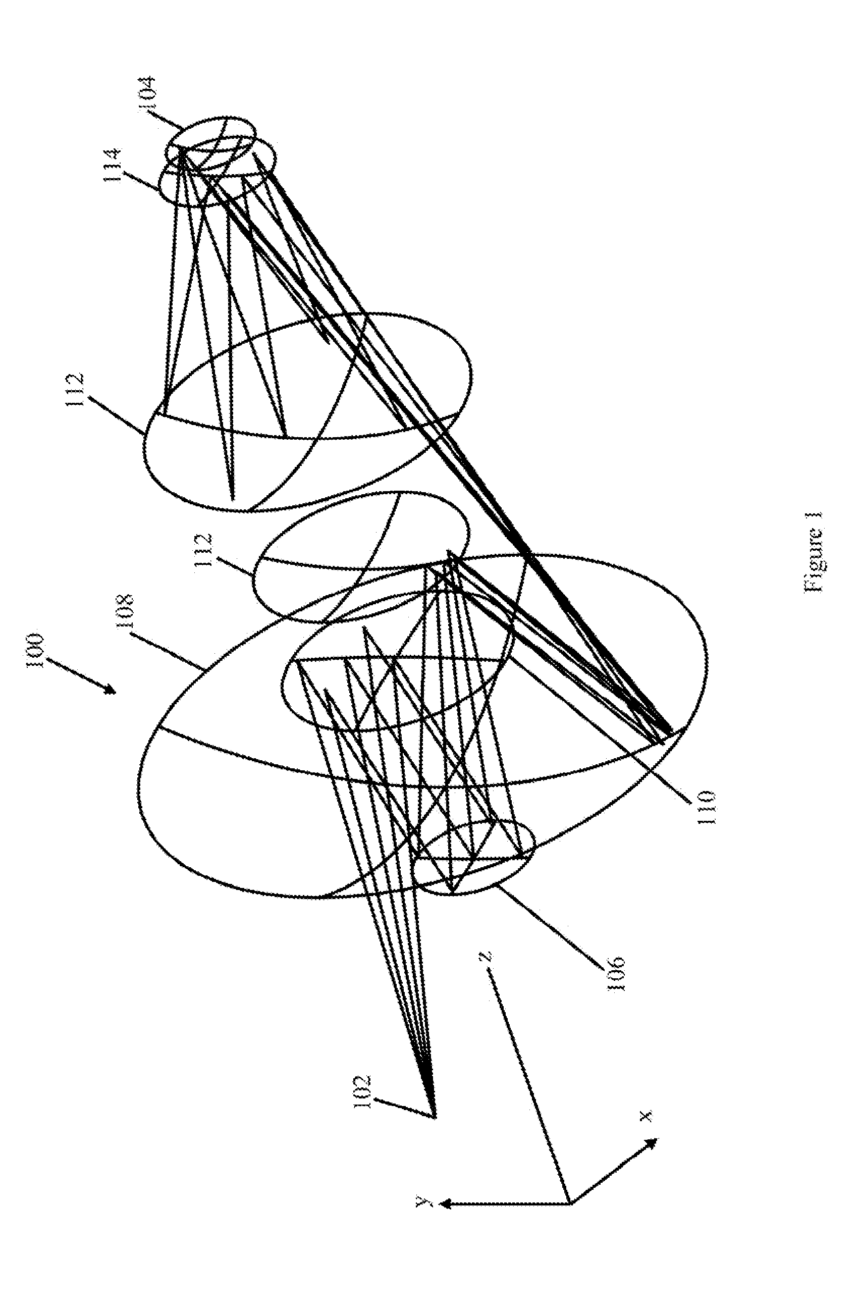
[0026]FIG. 1 illustrates the general configuration of an optical structure 100, according to the principles of the present invention, which can be used as part of a lithographic imaging optical system. The optical structure 100 would form part of a lithographic imaging optical system in which an object (e.g. ...


PUM


Abstract

Optical structure and design concepts are provided, using a Y-Zernike polynomial, and by which optical components, optical components and optical structures, can be designed and produced, to image at extreme ultraviolet (EUV) wavelengths, at a relatively high NA (e.g. 0.35), with a relatively large field of view (e.g. 26×2 mm). Moreover, an optical structure produced according to the principles of the present invention has a small amount of asymmetry, which enables the components of the optical structure to be manufactured with current manufacturing techniques.

Description

BACKGROUND[0001]The present invention relates to structure and process for producing optical components and optical structures that are particularly useful in a lithographic imaging optical system.[0002]In imaging optical systems, e.g. microlithography imaging optical systems for imaging (“printing”) a wafer, there is a continuing need for optical structures that can image (“print”) small features on a sample such as a wafer that is imaged by the microlithography imaging system.[0003]In addition, in the applicants' experience, there is also a need for optical structures that can image relatively small wavelengths (e.g. in the extreme ultra violet range), at relatively high numerical aperture (NA) with a large field of view and with small residual aberrations. Such optical structure is particularly desirable in a microlithography imaging optical system because it enables smaller features to be printed on a wafer with very small distortion.[0004]Moreover, in the applicants' experience...

Claims


Application Information

Patent Timeline
Patent Type & Authority Applications(United States)
IPC IPC(8): G02B17/06G06F17/50G06F17/10G02B5/10
CPCG02B17/0657
Inventor WILLIAMSON, DAVID M.SMITH, DANIEL G.
Owner NIKON CORP
Why Eureka
Try Eureka