
Path detection in trill networks

a trill network and path detection technology, applied in data switching networks, frequency-division multiplexes, instruments, etc., can solve the problems of limited bandwidth across the lan, trill networks lack many of the network control and management functions available in layer 3 networks, and the requirement of spanning trees of bridges can have substantial limitations

Active Publication Date: 2011-12-08
AVAGO TECH INT SALES PTE LTD
View PDF9 Cites 122 Cited by
  • Summary
  • Abstract
  • Description
  • Claims
  • Application Information

AI Technical Summary

Benefits of technology

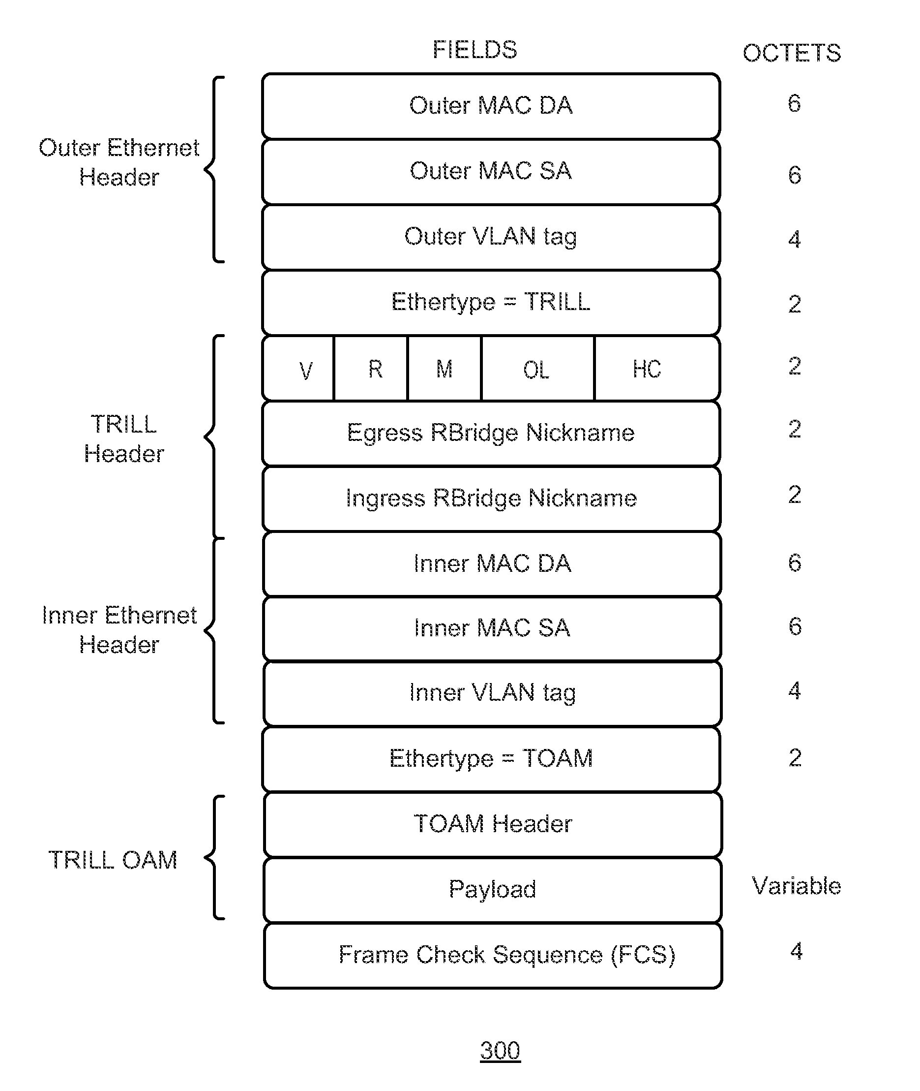
[0025]In a further variation, the Ethertype field is set as IP, and the inner transport protocol can be transmission control protocol (TCP) or user datagram protocol (UDP). The TRILL OAM frame is the payload of the TCP or UDP frame.

Problems solved by technology

However, the spanning tree requirement of bridges can have substantial limitations.
With spanning trees, the bandwidth across the LAN is limited because traffic flows over a subset of links forming a single tree or a small number of superimposed trees.
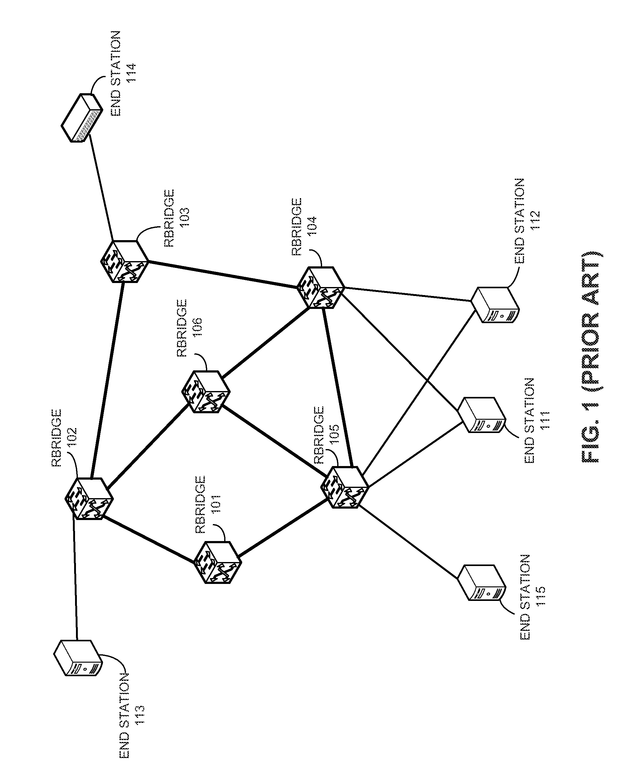
However, at present, TRILL networks lack many of the network control and management functions available in layer-3 networks.

Method used


Image

  • Path detection in trill networks
  • Path detection in trill networks
  • Path detection in trill networks

Examples


Embodiment Construction

[0045]The following description is presented to enable any person skilled in the art to make and use the invention, and is provided in the context of a particular application and its requirements. Various modifications to the disclosed embodiments will be readily apparent to those skilled in the art, and the general principles defined herein may be applied to other embodiments and applications without departing from the spirit and scope of the present invention. Thus, the present invention is not limited to the embodiments shown, but is to be accorded the widest scope consistent with the claims.

Overview

[0046]In embodiments of the present invention, the problem of route detection between TRILL nodes is solved by allowing a source node to send a number of path-detecting request packets to a destination node and determining whether corresponding response packets are received. During operation, the source node constructs a number of path-detecting request packets having incremental hop ...


PUM


Abstract

One embodiment of the present invention provides a system for detecting a path between two nodes. During operation, the system transmits a network-testing request frame, which includes a time-to-live (TTL) field within a Transparent Interconnection of Lots of Links (TRILL) header, from a source node to a destination node. In response to receiving a network-testing response frame sent from an intermediate node, the system increments the TTL value by 1 and re-transmits the network-testing frame to the destination node. In response to receiving a network-testing response frame sent from the destination node, the system determines a path between the source node and the destination node. The network-testing request or response frames is not processed on an Internet Protocol (IP) layer.

Description

RELATED APPLICATIONS[0001]This application claims the benefit of U.S. Provisional Application No. 61 / 350,830, Attorney Docket Number BRCD-3018.0.1.US.PSP, entitled “Path Detection in TRILL Networks,” by inventors Suresh Vobbilisetty, Phanidhar Koganti, and Arun Mahajan, filed 2 Jun. 2010, and U.S. Provisional Application No. 61 / 380,831, Attorney Docket Number BRCD-3018.0.2.US.PSP, entitled “Path Detection in TRILL Networks,” by inventors Suresh Vobbilisetty, Phanidhar Koganti, and Arun Mahajan, filed 8 Sep. 2010, the disclosures of which are incorporated by reference herein.[0002]The present disclosure is related to U.S. patent application Ser. No. 12 / 725,249 (attorney docket number BRCD-112-0439US), entitled “REDUNDANT HOST CONNECTION IN A ROUTED NETWORK,” by inventors Somesh Gupta, Anoop Ghanwani, Phanidhar Koganti, and Shunjia Yu, filed 16 Mar. 2010;[0003]U.S. patent application Ser. No. 12 / 730,749 (attorney docket number BRCD-3009.1.US.NP), entitled “METHOD AND SYSTEM FOR EXTEND...

Claims


Application Information

Patent Timeline
Patent Type & Authority Applications(United States)
IPC IPC(8): H04L12/26
CPCH04L43/10H04L43/0811
Inventor VOBBILISETTY, SURESHKOGANTI, PHANIDHARMAHAJAN, ARUN
Owner AVAGO TECH INT SALES PTE LTD
Learn More