
Fullerene based hydrogen storage system

a hydrogen storage system and fullerene technology, applied in the field of carbon-based hydrogen storage, can solve the problems of a large dependence on gasoline in these vehicles, the world's energy problems, and the current technology cannot store hydrogen at a sufficient weight percentag

Inactive Publication Date: 2011-12-08
THE UNITED STATES OF AMERICA AS REPRESENTED BY THE SECRETARY OF THE NAVY
View PDF2 Cites 13 Cited by
  • Summary
  • Abstract
  • Description
  • Claims
  • Application Information

AI Technical Summary

Benefits of technology

[0008]The present invention is directed to an apparatus and method for storing hydrogen using fullerenes between graphene sheets as the storage medium. A fullerene is any molecule composed entirely of carbon, in the form of a hollow sphere, ellipsoid or tube. Spherical fullerenes are also called buckyballs, and cylindrical fullerenes are called carbon nanotubes or buckytubes. Fullerenes are similar in structure to graphite, which is composed of stacked graphene sheets of linked hexagonal rings; but they may also contain pentagonal (or sometimes heptagonal) rings. This invention is directed to a pillared geometry of single-walled fullerenes separating parallel graphene sheets. T

Problems solved by technology

Hydrogen has the potential to ameliorate the world's energy problems, but at the present time current technology cannot store hydrogen at a sufficient weight percentage.
Although this is a start, there is still a large dependence on gasoline in these vehicles.
The main problem is that modern technology cannot enable the auto manufacturers to design a car solely powered by hydrogen while maintaining the goal of 300 miles per tank.
This problem lies in the onboard storage capacity for hydrogen.
However, in this form of hydrogen storage, advances in storage capacity are based on advances in insulation technology and not on hydrogen itself.

Method used


Image

  • Fullerene based hydrogen storage system
  • Fullerene based hydrogen storage system
  • Fullerene based hydrogen storage system

Examples


Embodiment Construction

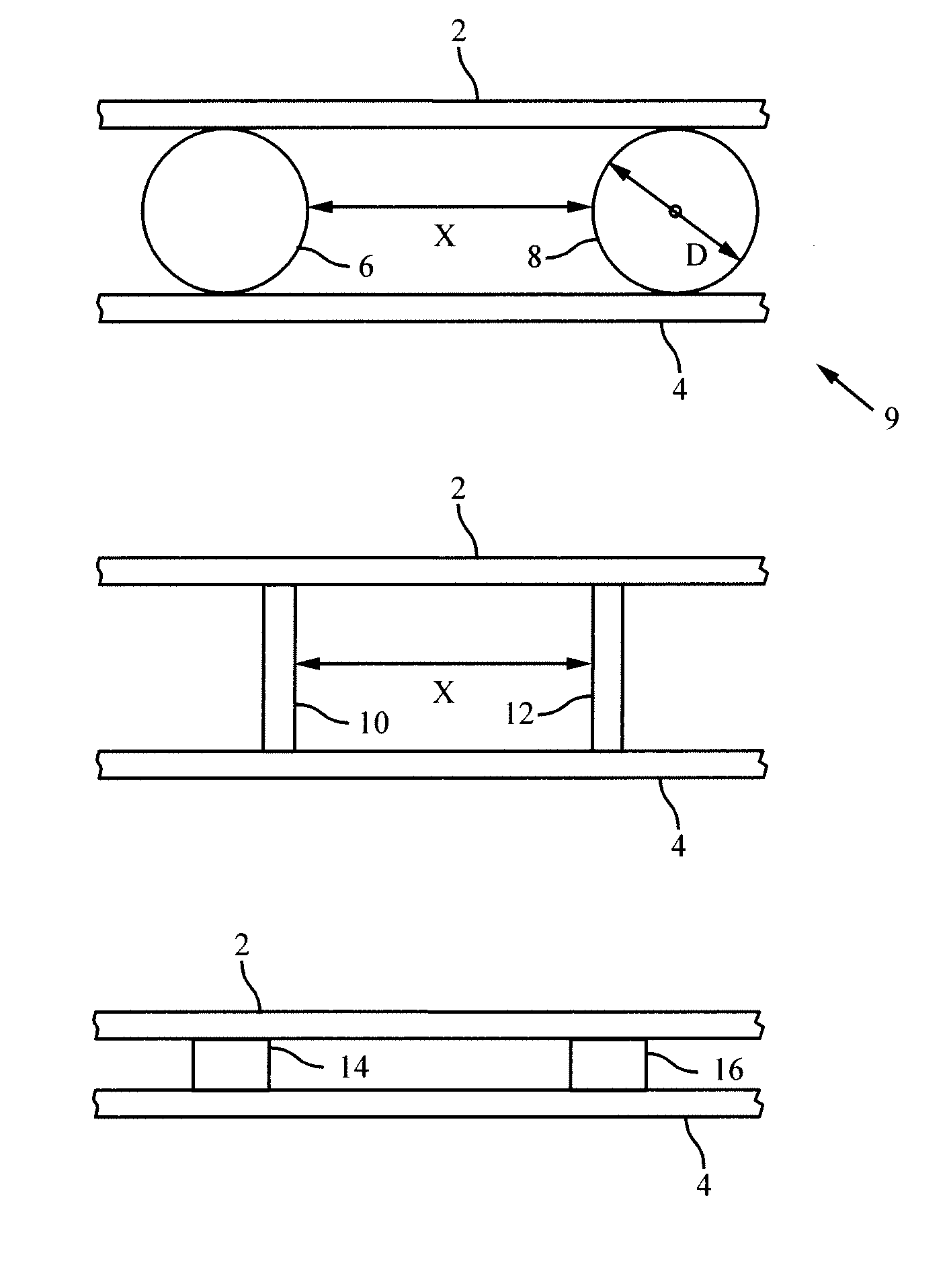
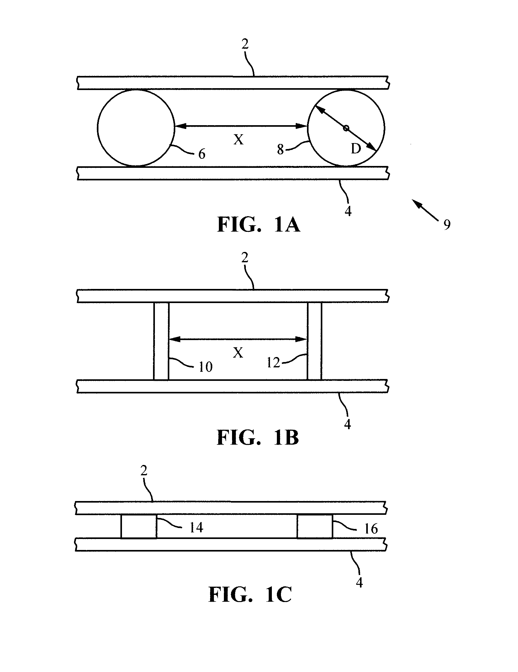
[0019]FIG. 1A represents a pair of graphene sheets 2 (a first graphene sheet) and 4 (a second graphene sheet) spaced apart by a pair of graphene spheres 6 and 8, which are commonly called “buckyballs.” It is to be understood that the arrangement of spheres 6 and 8 of FIG. 1 repeats periodically between the two graphene sheets 2 and 4. The spheres 6 and 8 preferably form a rectangular array and preferably have diameters D in the range of 5 Å (angstroms) to 15 Å and are spaced apart by a distance X that, in one embodiment, is in the range of 10 Å to 500 Å. In one embodiment, graphene sheets 2 and 4 are rectangular in shape with sides of up to 1 m in length and, in one embodiment, are spaced apart by 5 Å to 20 Å. There may be additional graphene sheets (not shown) and spheres (not shown) arranged to form a stack 9 of graphene sheets with an array of spheres between facing adjacent graphene sheets.

[0020]FIG. 1B shows a structure similar to that of FIG. 1A with the difference being that ...


PUM


Abstract

A hydrogen storage structure includes a plurality of graphene sheets arranged to form a stack with a plurality of spacers between adjacent graphene sheets in the stack. In one embodiment, the spacers are arranged to provide a distance ranging between 5 Å and 20 Å between adjacent graphene sheets. In one embodiment, the spacers are formed as graphene spheres having a diameter that ranges from 5 Å to 15 Å. In another embodiment, the spacers are formed as graphene single-walled nanontubes having a length that ranges from 5 Å to 20 Å. In a further embodiment, the spacers are formed as graphene sheets having a thickness that ranges from 5 Å to 20 Å. In one embodiment, the plurality of graphene sheets is doped with lithium. In one embodiment, the lithium doping concentration is a ratio of one lithium atom per three carbon atoms.

Description

CROSS-REFERENCE TO RELATED APPLICATIONS[0001]This application claims the benefit of U.S. Provisional Application No. 61 / 153,922, filed Feb. 19, 2009, which is hereby incorporated in its entirety by reference.BACKGROUND OF THE INVENTION[0002]1. Field of the Invention[0003]The present invention relates generally to apparatus and methods for storing hydrogen for use as a fuel. In particular, this invention relates to storing hydrogen in carbon-based media, such as for use in alternative fuel vehicles.[0004]2. Description of the Related Art[0005]As the 21st century progresses the need for alternative forms of energy continues to rise. In the wake of ever-rising oil prices suitable alternative energy sources are necessary. One of the most attractive alternatives is hydrogen. Hydrogen has such an appeal because it can be easily created via electrolysis of water, a resource that is much more abundant than foreign oil. The successful use of hydrogen could allow the United States to reduce i...

Claims


Application Information

Patent Timeline
IPC IPC(8): C01B3/02B32B5/00B32B5/16B32B9/04
CPCB82Y30/00C01B3/0021Y10T428/25Y10T428/26Y10T428/30Y02E60/325Y02E60/32
Inventor PHILLIPS, III, CHARLES WASHINGTONSCANDRETT, CLYDE L.LLOYD, JOHN R.LUO, TENGFEI
Owner THE UNITED STATES OF AMERICA AS REPRESENTED BY THE SECRETARY OF THE NAVY
Learn More