Fluidic endoscope tip locator

a fluoroscope and endoscope technology, applied in the field of fluidic endoscope tip locators, can solve the problems of inability to easily image fluoroscope images, inability to femoral head or other organs or tissues of other types of endoscopic surgical sites, and inability to easily form cannulas of transparent plastic, etc., to achieve convenient connection, improve fluid and air transmission characteristics, and facilitate receipt

Inactive Publication Date: 2011-12-08
BRANNON JAMES K
View PDF5 Cites 5 Cited by
  • Summary
  • Abstract
  • Description
  • Claims
  • Application Information

AI Technical Summary

Benefits of technology

[0008]An embodiment of the invention employs a transparent endoscopic portal instrument or scope having an enlarged membrane chamber communicating with an elongated portal cannula terminating distally in a portal cannula tip. The portal cannula tip may be conically tapered and cut off at an angle to the longitudinal axis of the portal cannula. The membrane chamber will remain external to the patient, while the cannula will be extended through an incision toward the surgical site. A side port communicates with the membrane chamber. A rear port communicates with the membrane chamber and is aligned with the portal cannula, but is separated from the membrane chamber by a portal membrane or diaphragm. The membrane has a slit cut therethrough which is aligned with the portal cannula and which normally closed. An embodiment of the portal scope has a crossed pair of slits which intersect at substantially a right angle. The portal scope is employed to establish and maintain a pathway from an external incision in the patient to the surgical site which may, for example, be a knee joint, a hip joint, or the like. The portal scope enables other endoscopic instruments to be passed therethrough to the surgical site, as well as the passage of fluids to and from the surgical site. The portal scope is formed of a transparent plastic which enables viewing through portions thereof, especially the cannula and tip.
[0012]In an exemplary application, the tip of the trephine cannula is telescoped over a guide wire which has been previously emplaced in the surgical site, as by use of a fluoroscope. The tip of the portal scope, with the trephine tip axially extending theralong, is inserted through an external incision and advanced carefully toward the surgical site along the guide wire, with the surgeon observing the transparent portal scope. Fluid from the fluid source exits the trephine tip, while the negative pressures is presented through an annular cannula gap between the trephine cannula and the portal cannula. Depending on the pressure differential between the tip of the portal scope and the rear port, the negative pressure may be relieved somewhat by air passing through the membrane slits with the trephine cannula passing therethrough, based upon pressure differentials. Small amounts of fluid exiting the trephine tip may be drawn into the cannula gap, for example, if there is a blockage at the portal tip by intervening tissues encountered between the incision and the surgical site. When the trephine tip enters the surgical site, such as a joint capsule, the fluid exiting therefrom fills the site. As the portal tip enters the surgical site, blockage of the portal cannula tip is reduced and the fluid within the surgical site is drawn therein, enabling a substantially increased flow of the fluid into the portal tip and back through the portal cannula toward the side port. Such increased flow is visually observable by the surgeon and indicates that the portal tip has entered the surgical site. At this point, further insertion of the portal tip into the surgical site is halted, and the trephine instrument can be withdrawn from the portal scope. Other instruments can now be extended through the portal scope for diagnosis and surgical treatment as indicated by the conditions observed.
[0013]A removable outflow adapter may be rearwardly associated with the trephine, the removable outflow adapter having a main passage extending between a terminus towards a male port and a radial passage extending radially outward from the main passage. A female connector associated with the proximal rear port may be adapted for receipt of the outflow adapter at a male port extending from one end of the main passage. As illustrated, the male port as illustrated may include an annular ring extending towards an annular taper. The terminus and the radial passage are generally positioned for fluidic communication with the trephine so that the outflow adapter may be used to facilitate connections to the vacuum source or irrigant sources with for example, the radial passage. In addition, the outflow adapter may facilitate receipt of various instruments or manual control of entering or exiting fluid from the surgical site with a rear aperture positioned opposite the male port and associated with the outflow adapter.
[0014]In an alternative embodiment, the present invention provides for an improved tip position determining assembly for visually determining the entry of the instrument tip into the internal surgical site. In this embodiment, a transparent endoscopic portal includes a proximate chamber housing the membrane and having a rear port extending from the rear of the chamber and an elongated portal cannula extending forwardly from the chamber towards the portal tip. The rear port is generally axially aligned with the portal cannula providing better fluid and air transmission characteristics.

Problems solved by technology

Although often more complicated in some ways for the surgeon, minimally invasive techniques result in less trauma to the patient and less scarring because of much smaller incisions thereby promoting faster healing and reducing possibilities for infections.
The portal scope is of such a diameter that incorrect placement of the distal tip within the joint capsule could injure the femoral head or other organs or tissues of other types of endoscopic surgical sites.
However, such a portal scope with a cannula formed of a transparent plastic would be radiotransparent and not easily imaged with a fluoroscope.

Method used


Image

  • Fluidic endoscope tip locator
  • Fluidic endoscope tip locator
  • Fluidic endoscope tip locator

Examples


Embodiment Construction

[0026]As required, detailed embodiments of the present invention are disclosed herein; however, it is to be understood that the disclosed embodiments are merely exemplary of the invention, which may be embodied in various forms. Therefore, specific structural and functional details disclosed herein are not to be interpreted as limiting, but merely as a basis for the claims and as a representative basis for teaching one skilled in the art to variously employ the present invention in virtually any appropriately detailed structure.

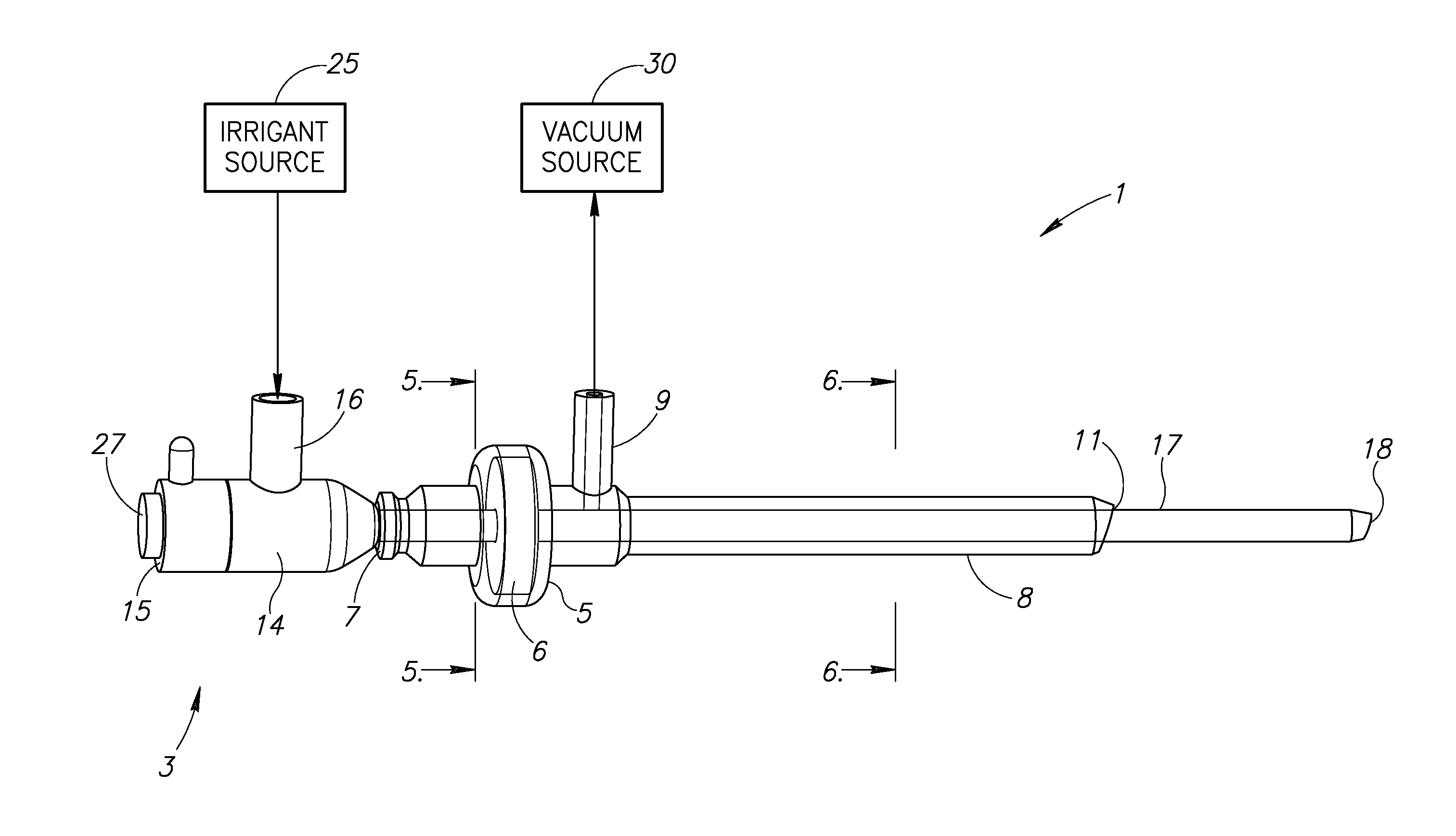
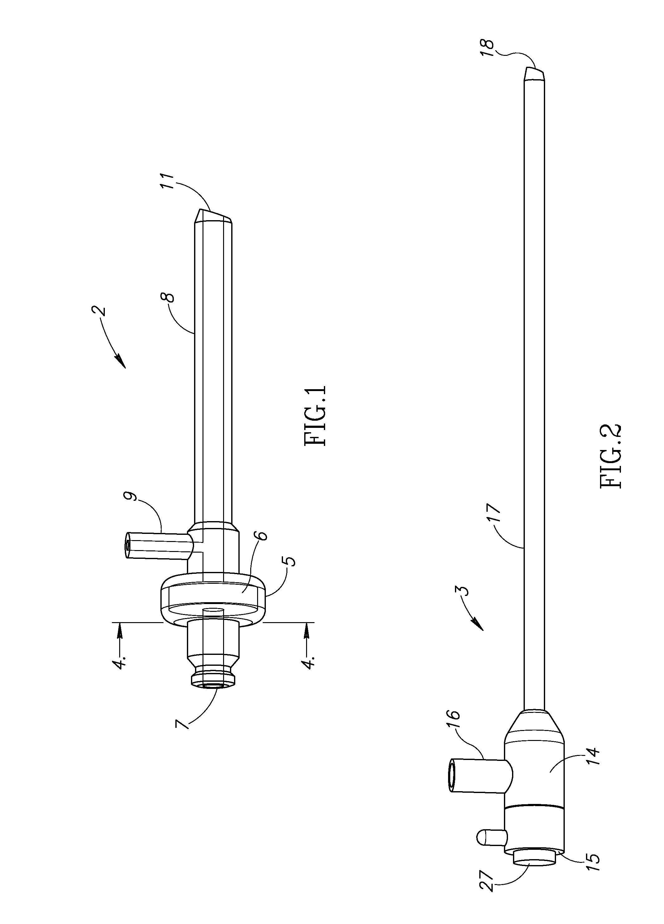
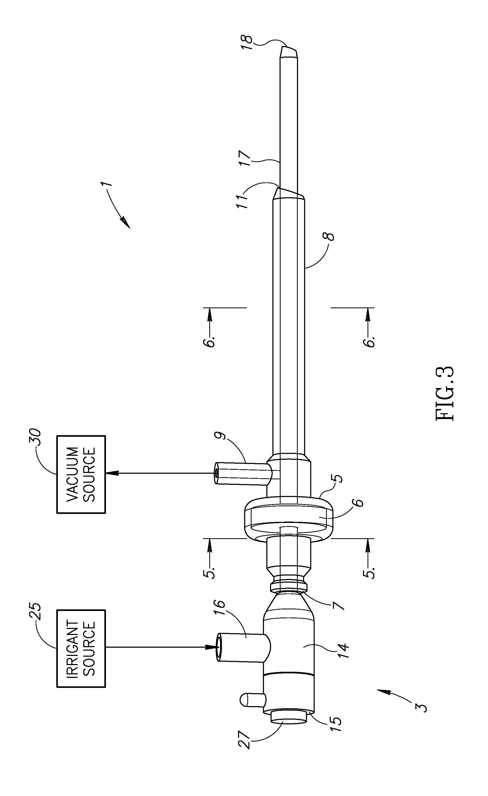
[0027]Referring to the drawings in more detail, the reference numeral 1 (FIGS. 3 and 7-9) generally designates an embodiment of a tip position determining assembly 1 of endoscopic instruments for determining fluidically the entry of a tip or tips of the instruments into an internal surgical site. Referring to FIGS. 1 and 2, the illustrated assembly 1 includes an endoscopic portal instrument or scope 2 (FIG. 1) and a trephine instrument or trephine 3 (FIG. 2)....


PUM


Abstract

The present invention provides an improved tip position determining assembly for visually and fluidically determining the entry of an instrument tip into an internal surgical site, the assembly comprising an endoscopic portal having a chamber housing a membrane having a plurality of slit openings associated with a slit for sealingly receiving a trephine and an irrigant and vacuum source connectably secured to said assembly for observing an instrument tip entering a surgical site.

Description

CROSS-REFERENCE TO RELATED APPLICATION[0001]This application claims the benefit of the prior filed U.S. provisional application No. 61 / 266,908 filed Dec. 4, 2009 which is incorporated herein by reference.FIELD OF THE INVENTION[0002]The present invention is broadly directed to improvements in instruments for endoscopic surgery and, more particularly, for detecting the entry of a tip of an endoscopic instrument assembly within a surgical site within a patient by fluidic means.BACKGROUND OF THE INVENTION[0003]Modern surgery tends toward minimally invasive techniques whenever possible. Although often more complicated in some ways for the surgeon, minimally invasive techniques result in less trauma to the patient and less scarring because of much smaller incisions thereby promoting faster healing and reducing possibilities for infections. In general, minimally invasive surgeries involve making one or more small incisions at appropriate locations and inserting tubular devices through the ...

Claims


Application Information

Patent Timeline
Patent Type & Authority Applications(United States)
IPC IPC(8): A61B1/018A61B1/12
CPCA61B1/00154A61B1/018A61B1/015A61B1/01
Inventor BRANNON, JAMES K.
Owner BRANNON JAMES K
Why Eureka
Try Eureka