Device mounter head and device mounting method using the same

a technology of device mounter and mounting method, which is applied in the direction of manufacturing tools, metal-working machine components, transportation and packaging, etc., can solve the problems of time delay, inability to control precisely the timing of forming, and pipeline communication time delay, so as to reduce the effective time delay in controlling air pressure and simple control scheme , the effect of simple structur

Inactive Publication Date: 2011-12-15
HANWHA AEROSPACE CO LTD
View PDF2 Cites 8 Cited by
  • Summary
  • Abstract
  • Description
  • Claims
  • Application Information

AI Technical Summary

Benefits of technology

[0010]One or more exemplary embodiments provide a device mounter head having a simple structure and a simple controlling scheme, and for reducing effectively a time delay in controlling air pressure of an inlet port of a nozzle spindle.

Problems solved by technology

However, a time delay may occur in a pipeline communicating with the inlet port of the nozzle spindle.
In addition, the time delay may occur also in a solenoid valve disposed inside the pipeline.
Like this, in a case where the time delay occurs in the device mounter head, it is not possible to control precisely a timing of forming or clearing negative pressure in the inlet port of the nozzle spindle.
As a result, a time required for a device mounting process increases.
In addition, in the device mounter head, a control for the air pressure of the inlet port and a control for the movement of the nozzle spindle are independent from each other, and thus, hardware of the device mounter head is complicated.

Method used


Image

  • Device mounter head and device mounting method using the same
  • Device mounter head and device mounting method using the same
  • Device mounter head and device mounting method using the same

Examples


Embodiment Construction

[0030]Hereinafter, exemplary embodiments will be described in detail with reference to the attached drawings.

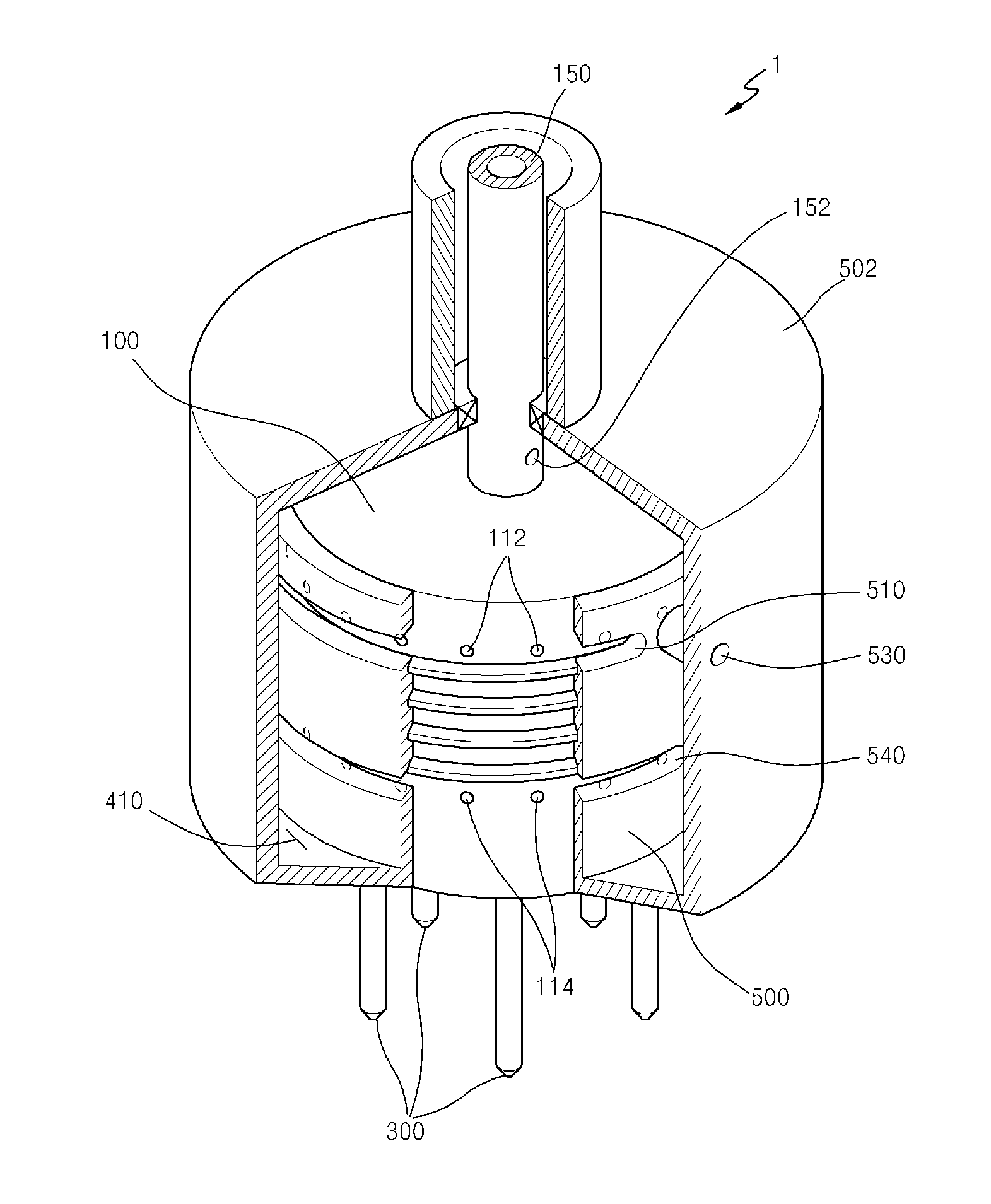
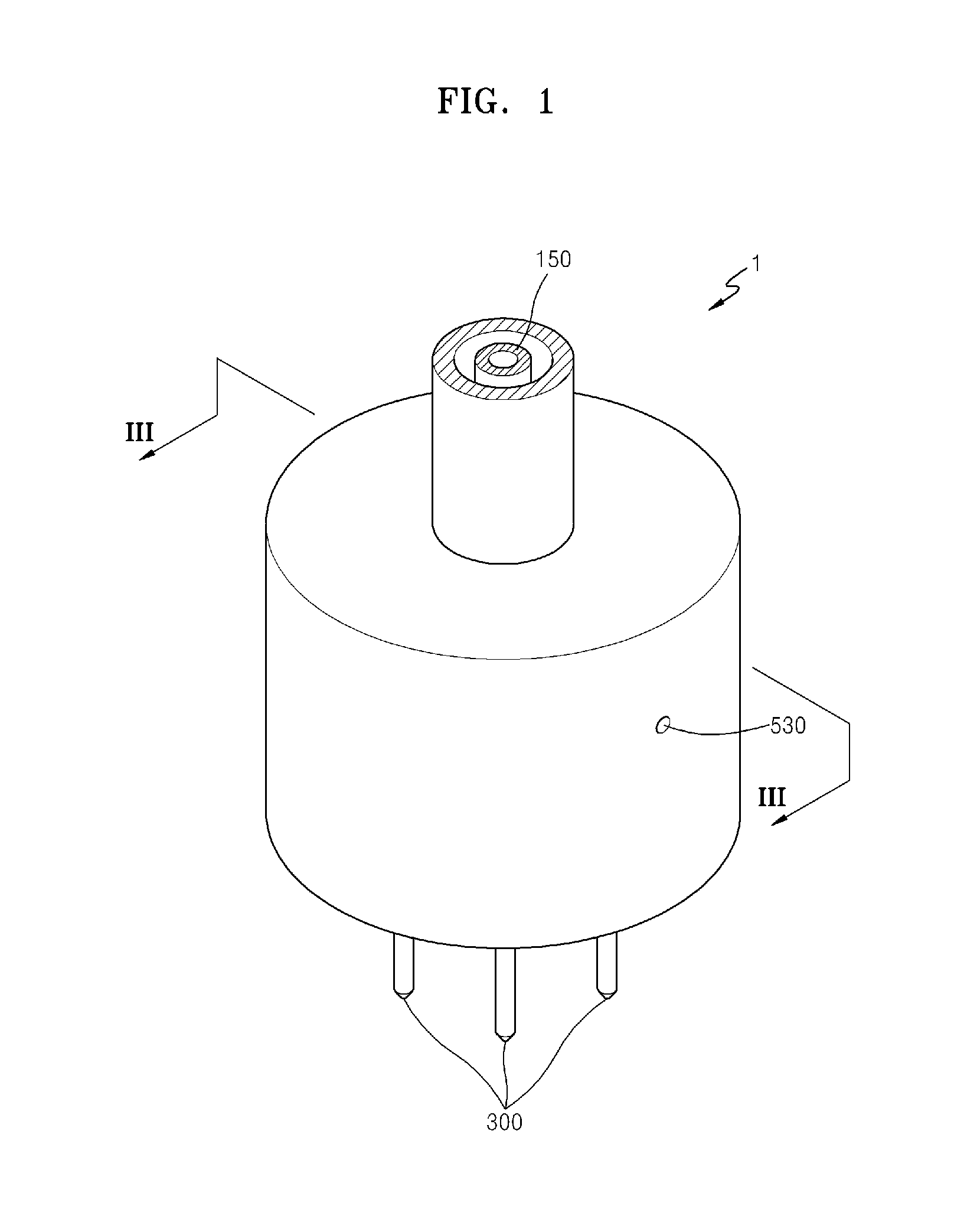
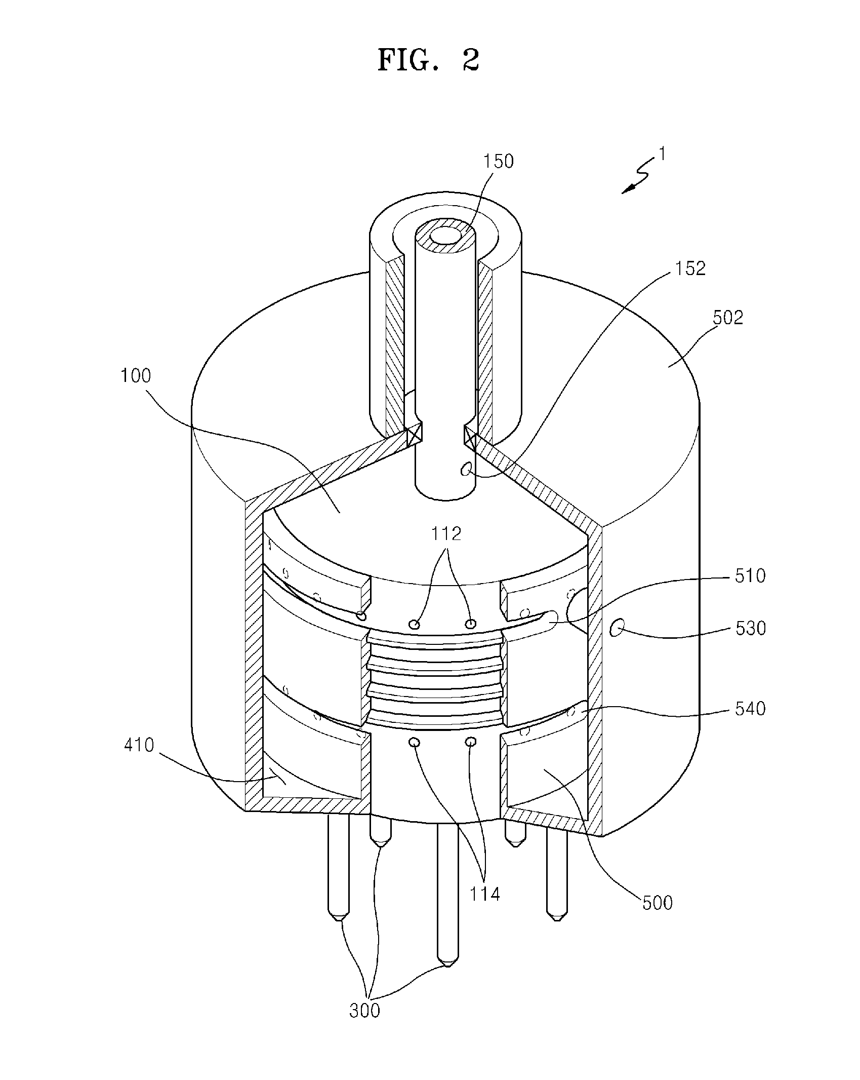
[0031]FIG. 1 is a perspective view of a device mounter head according to an exemplary embodiment, FIG. 2 is a perspective view of the device mounter head of FIG. 1 in which a part is cut out, and FIG. 3 is a cross-sectional view taken along a line III-III of the device mounter head of FIG. 1. FIG. 4 is a perspective view illustrating a configuration of a part of the device mounter head of FIG. 1, and FIG. 5 is a perspective view illustrating the configuration of the part of FIG. 4 together with a configuration of another part of the device mounter head of FIG. 1. FIG. 6A is a cross-sectional view illustrating roughly a part of the device mounter head of FIG. 1 to show partially an operation state of the device mounter head of FIG. 1, and FIG. 6B is a diagram illustrating roughly an arrangement of a configuration of a part in a case where the device mounter head of FIG. 1 is i...


PUM

PropertyMeasurementUnit
pressureaaaaaaaaaa
distanceaaaaaaaaaa
air pressureaaaaaaaaaa

Abstract

A device mounter head and a device mounting method using the device mounter head are provided. The device mounter head includes: a cylinder block unit including at least one cylinder in which a piston unit moving along the at least one cylinder is disposed; a pressure control unit which controls pressure inside and outside the at least one cylinder so that the piston moves along the at least one cylinder based on the controlled pressure; and a nozzle which is connected to the piston unit, and includes an inlet exposed to an atmosphere outside the cylinder block unit and a nozzle communication vent connected to the inlet and provided with the controlled pressure, wherein the inlet is configured to suck, grab and release a component using the controlled pressure.

Description

CROSS-REFERENCE TO RELATED PATENT APPLICATION[0001]This application claims priority from Korean Patent Application No. 10-2010-0056199, filed on Jun. 14, 2010, in the Korean Intellectual Property Office, the disclosure of which is incorporated herein in its entirety by reference.BACKGROUND[0002]1. Field[0003]Apparatuses and methods consistent with exemplary embodiments relate to a device mounter head, and more particularly, to a device mounter head for mounting components on a substrate and the like after grabbing the components and transferring the components and a device mounting method using the device mounter.[0004]2. Description of the Related Art[0005]A device mounter head operates by grabbing electronic components, transferring the electronic components, and then mounting the electronic components on a substrate, as an apparatus for mounting electronic components such as semiconductors and the like on a substrate.[0006]The device mounter head includes a nozzle spindle with an...

Claims


Application Information

Patent Timeline
Patent Type & Authority Applications(United States)
IPC IPC(8): B23Q7/04B23P19/00
CPCH05K13/0408H05K13/0452H05K13/0413H05K13/04Y10T29/49998Y10T29/53991Y10T29/53174Y10T29/53178Y10T29/53191Y10T29/53Y10T29/5313H05K13/0409H05K13/041B65G47/91
Inventor BAN, JONG-EOK
Owner HANWHA AEROSPACE CO LTD
Why Eureka
Try Eureka