
Liquid-gas heat exchanger

a heat exchanger and liquid gas technology, applied in the field of liquid gas heat exchangers, can solve the problems of heavy foam, high cost, and high exit achieve the effects of reducing the temperature of the compressor, and reducing the heat exchange efficiency

Inactive Publication Date: 2011-12-15
PURDUE RES FOUND INC
View PDF9 Cites 33 Cited by
  • Summary
  • Abstract
  • Description
  • Claims
  • Application Information

AI Technical Summary

Benefits of technology

[0015]It will be appreciated that the various apparatus and methods described in this summary section, as well as elsewhere in this application, can be expressed as a large number of different combinations and subco

Problems solved by technology

However, for supersonic engines, the compressor exit temperature is too high to cool the turbine blades; in some cases a heat exchanger may be needed to cool the compressor bleed air.
The use of air-fuel heat exchanger in a supersonic engine can result in added pressure drop incurred in both the air and the fuel.
Their tests revealed that the foam is heavy and expensive.

Method used


Image

  • Liquid-gas heat exchanger
  • Liquid-gas heat exchanger
  • Liquid-gas heat exchanger

Examples


Embodiment Construction

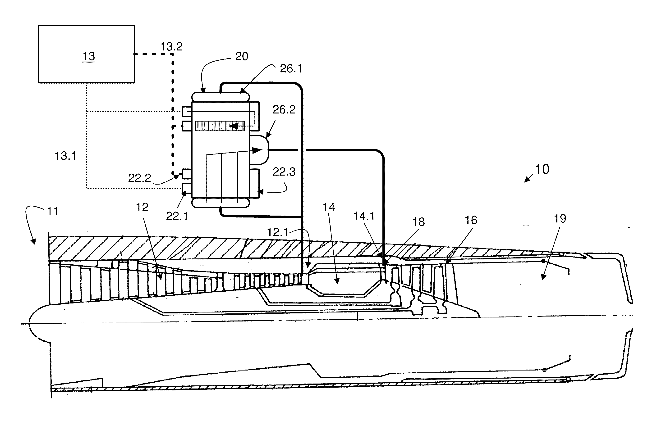
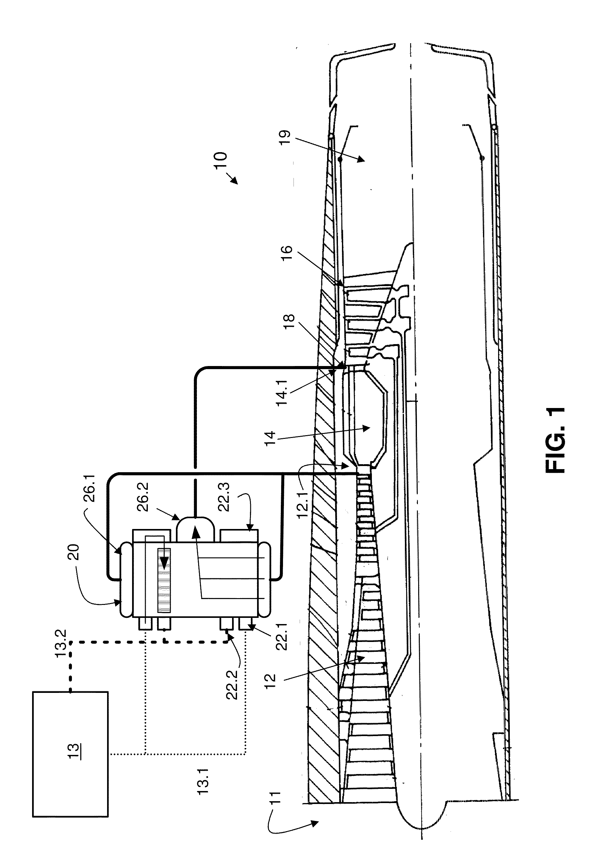
[0053]For the purposes of promoting an understanding of the principles of the invention, reference will now be made to the embodiments illustrated in the drawings and specific language will be used to describe the same. It will nevertheless be understood that no limitation of the scope of the invention is thereby intended, such alterations and further modifications in the illustrated device, and such further applications of the principles of the invention as illustrated therein being contemplated as would normally occur to one skilled in the art to which the invention relates. At least one embodiment of the present invention will be described and shown, and this application may show and / or describe other embodiments of the present invention. It is understood that any reference to “the invention” is a reference to an embodiment of a family of inventions, with no single embodiment including an apparatus, process, or composition that must be included in all embodiments, unless otherwis...


PUM


Abstract

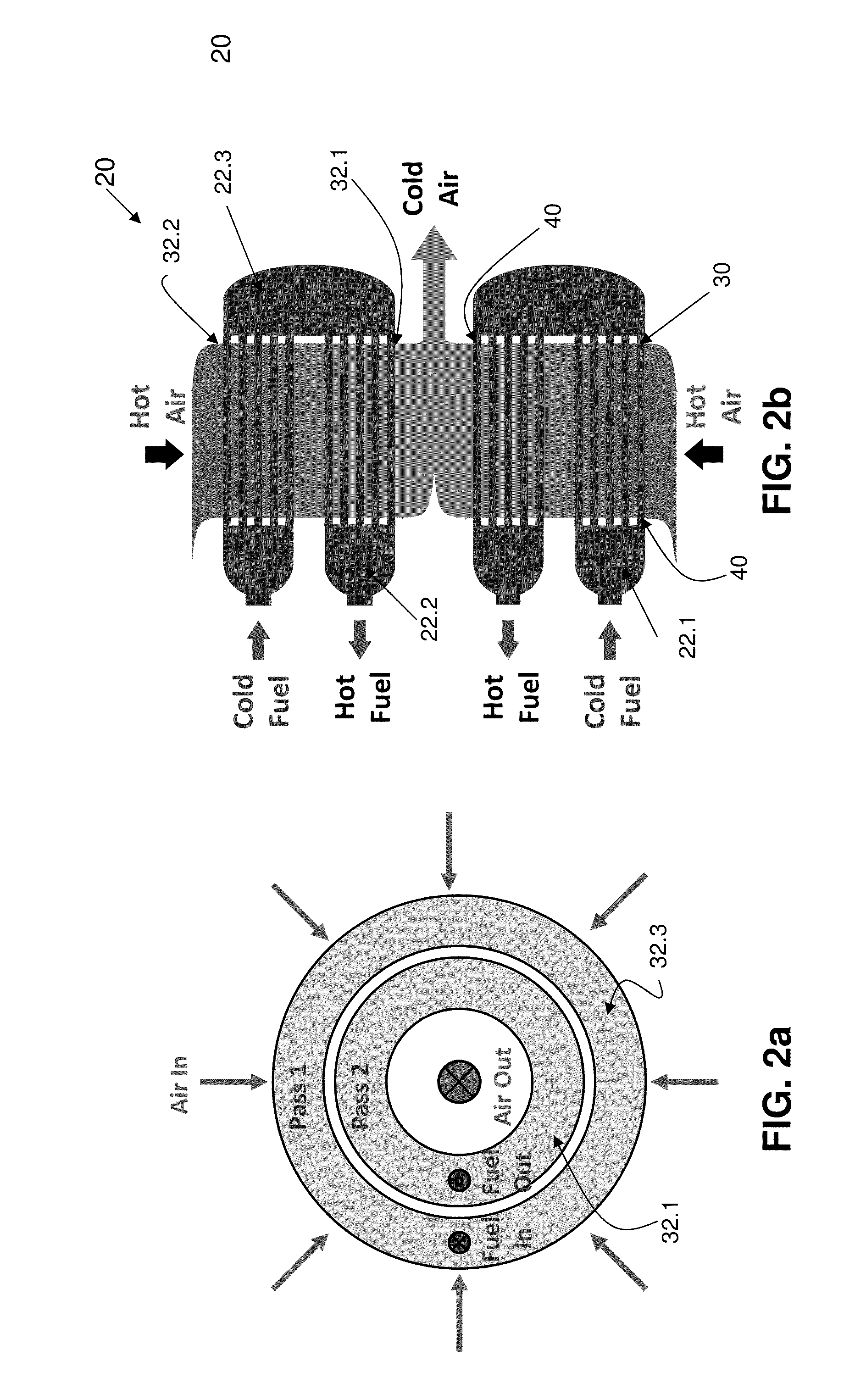
The heat exchanger includes a large number of small, closely-spaced modules. Within each module of one embodiment, the fuel flows through a series of parallel micro-channels, while the air flows externally over rows of short, straight fins perpendicular to the direction of fuel flow. A theoretical model was developed to predict the thermal performance of the module for various operating conditions. To confirm the accuracy of the model, a module was constructed and tested using water to simulate the aircraft fuel.

Description

CROSS REFERENCE TO RELATED APPLICATION[0001]This application claims the benefit of priority to U.S. Provisional Patent Application Ser. No. 61 / 156,133, filed Feb. 27, 2009, entitled HEAT EXCHANGER FOR HIGH MACH NUMBER JET ENGINE, incorporated herein by reference.FIELD OF THE INVENTION[0002]Various embodiments of the present invention pertain to liquid-gas heat exchangers, and in particular to fuel-air heat exchangers used in the fuel system of an engine.BACKGROUND OF THE INVENTION[0003]As the need for more fuel-efficient modes of transportation becomes an increasing global concern, improved technologies must be developed to meet higher standards of fuel-efficiency without great sacrifices to vehicle performance. This search for greater economy extends to every mode of transportation, from engines in automobiles to gas turbine engines in aircraft. Within the high Mach gas turbine industry, strides have been made to improve aircraft efficiency; however materials and designs are contin...

Claims


Application Information

Patent Timeline
IPC IPC(8): F02C6/08F28D15/00
CPCF02C7/224F28D7/1623F28F1/022F05D2260/22141Y02E20/14Y02T50/671Y02T50/676F28F1/28Y02T50/60
Inventor MUDAWAR, ISSAM
Owner PURDUE RES FOUND INC
Learn More