Test fixture for automotive wiper systems

Inactive Publication Date: 2011-12-15
ROBERT BOSCH CORP +1
View PDF0 Cites 6 Cited by
  • Summary
  • Abstract
  • Description
  • Claims
  • Application Information

AI Technical Summary

Benefits of technology

[0004]Resonant frequencies of test fixture support structures can introduce errors in test fixture measurements. The test fixture of the pre

Problems solved by technology

In particular, measuring forces at the vehicle to wiper linkage connection locations under realistic operating loads can be correlated to in-vehicl

Method used


Image

  • Test fixture for automotive wiper systems
  • Test fixture for automotive wiper systems
  • Test fixture for automotive wiper systems

Examples


Example

DETAILED DESCRIPTION OF THE DRAWINGS

[0015]For the purposes of promoting an understanding of the principles of the present disclosure, reference will now be made to the embodiments illustrated in the drawings, which are described below. The embodiments disclosed below are not intended to be exhaustive or limit the present system to the precise form disclosed in the following detailed description. Rather, the embodiments are chosen and described so that others skilled in the art may utilize their teachings. Therefore, no limitation of the scope of the claimed present system is thereby intended. The present system includes any alterations and further modifications of the illustrated devices, systems and described methods and further applications of the principles of the present disclosure which would normally occur to one skilled in the art. Corresponding reference characters indicate corresponding parts throughout the several views.

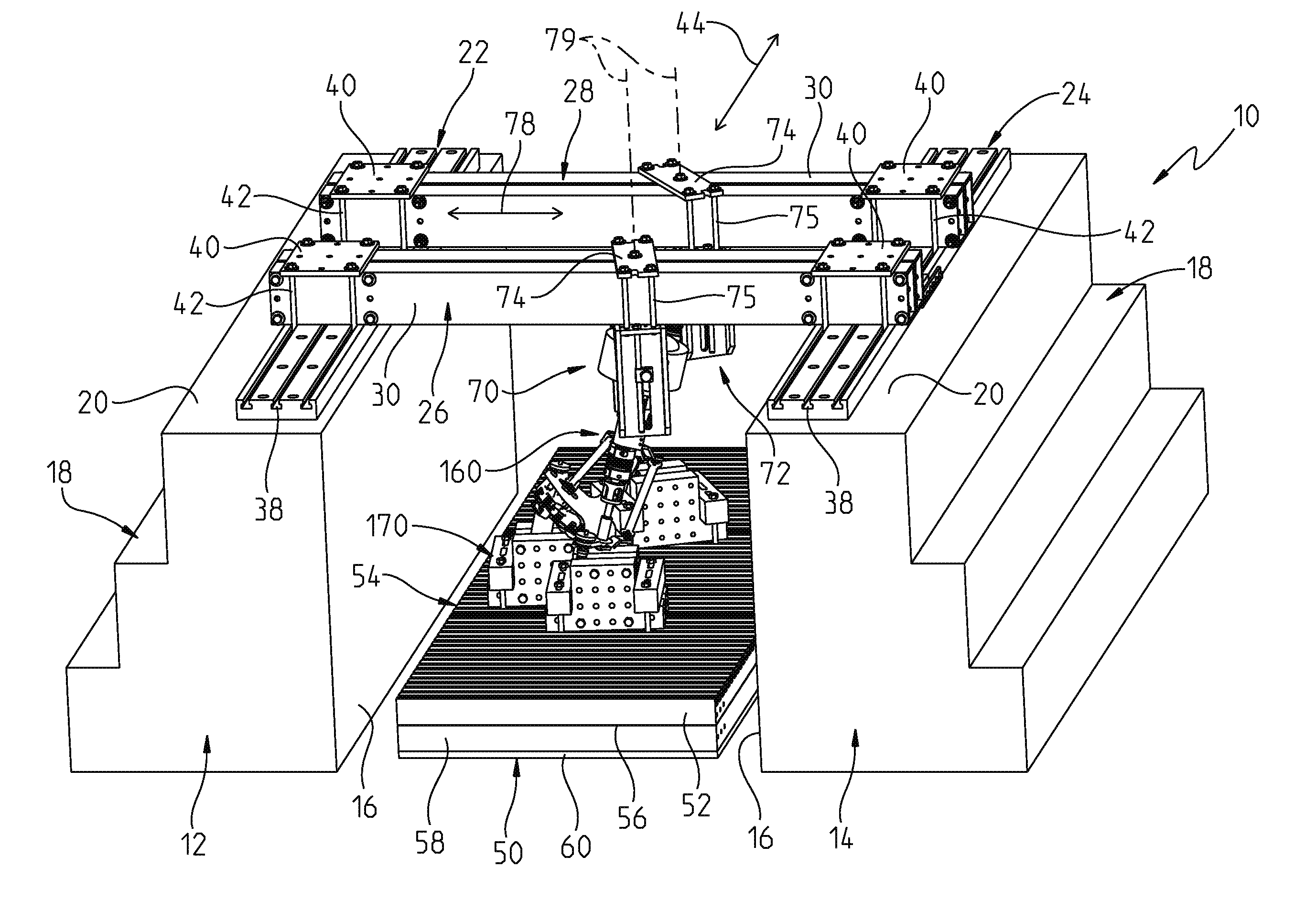
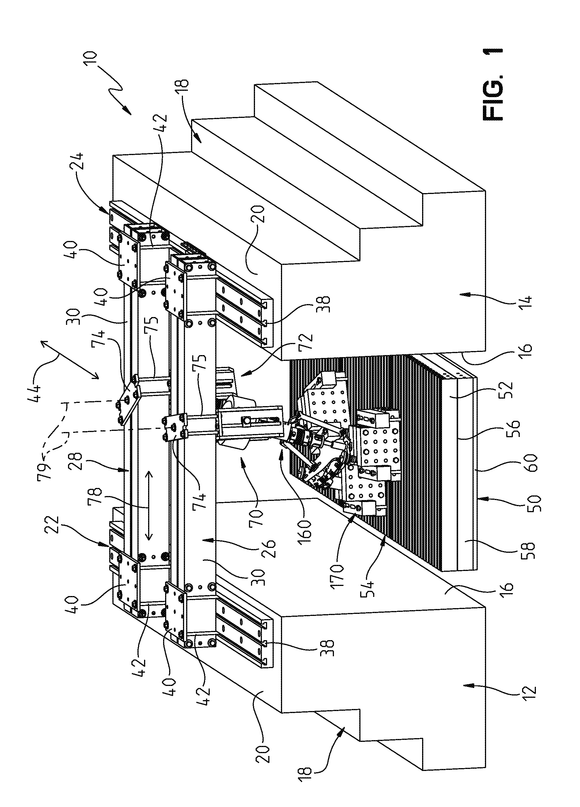
[0016]FIG. 1 illustrates a test fixture apparatus 10 ...


PUM


Abstract

A test fixture is provided for automotive wiper systems. The wiper system includes a plurality of connection points and one or more wiper arm connectors. The test fixture measures forces caused by the wiper system's operation at the plurality of connection points while a resistive torque is applied to each of the wiper arm connectors. The test fixture allows for multiple attachment configurations to accommodate the many wiper system configurations that exist.

Description

BACKGROUND AND SUMMARY[0001]The present disclosure relates to a fixture for testing operation of an electrically driven automotive component. More particularly, the present invention relates to a test fixture for testing operation of automotive wiper systems.[0002]Many different configurations of wiper systems exist for vehicles. It is desirable to test operational performance of these wiper systems under controlled conditions. In particular, measuring forces at the vehicle to wiper linkage connection locations under realistic operating loads can be correlated to in-vehicle noise performance of the wiper systems.[0003]The test fixture of the present disclosure measures the vehicle to wiper system connection location forces under an approximation of an infinite-mass boundary condition; this measurement method is known as a “blocked force measurement”. The test fixture of the present disclosure illustratively measures forces at the connection points between the wiper system and the ve...

Claims


Application Information

Patent Timeline
IPC IPC(8): G01L1/00G01L3/00G01D7/00
CPCB60S1/0469G01M99/007G01M99/005
Inventor NICGORSKI, II, DANA F.
Owner ROBERT BOSCH CORP
Why Eureka
Try Eureka