High Permeance Sulfur Tolerant Pd/Cu Alloy Membranes

Inactive Publication Date: 2011-12-15
WORCESTER POLYTECHNIC INSTITUTE
View PDF3 Cites 5 Cited by
  • Summary
  • Abstract
  • Description
  • Claims
  • Application Information

AI Technical Summary

Benefits of technology

[0013]The present invention has many advantages. For example, it is believed that membranes formed by the method have greater tolerance for sulfur. It is also believed that the membranes generally require lower annealing times

Problems solved by technology

However, small quantities of H2S present in the gas stream poison Pd membranes causing either a drastic reduction of the hydrogen permeance or irreparable damage to the membrane by forming a Pd4S layer.
Pd/Cu alloys have generated much research, not only because they do not exhibit hydrogen embrittlement even at room temperature but also because Pd/Cu alloys are more resistant to H2S poisoning than pure Pd when the Cu composition is in the fcc region of the Pd/Cu phase diagram. FIG. 1 is a Pd—Cu phase diagram overlaid with the relative permeability of Pd/Cu membranes to Pd membranes as a function of Cu content at 350° C. One of the disadvantages of fcc Pd/

Method used


Image

  • High Permeance Sulfur Tolerant Pd/Cu Alloy Membranes
  • High Permeance Sulfur Tolerant Pd/Cu Alloy Membranes
  • High Permeance Sulfur Tolerant Pd/Cu Alloy Membranes

Examples


example 1

Dense Pd Layer Formation (Tubular Membrane Only)

[0043]Pd was plated until no plating solution was found in the interior of the tube indicating that the membrane was “liquid dense,” usually after 2-3 plating rounds. The membrane would then be rinsed with deionized water and dried at 120° C. overnight. The He permeance would be measured and the membrane plated again. After the membrane was liquid dense, the membrane was plated with a vacuum by attaching the tube side to an aspirator or vacuum pump. A slight vacuum was used at first (550 ton) and if the level of the plating solution did not decrease, indicating that the membrane was “liquid dense”, the vacuum was increased to 380 torr. If the membrane was “liquid dense” at 380 ton then the vacuum was then increased to 75 ton to block the remaining pinholes. Between each round of plating, the membrane was dried and the He permeance measured. If the He leak of the membrane could not be detected at ΔP=2.3 bar at room temperature, the memb...

example 2

Cu Plating

[0044]In order to form a Pd / Cu bi-layer, a plating bath was used to plate Cu onto the coupons. Table 1 lists the Cu plating bath composition, as well as the composition of the Pd galvanic displacement bath, which is described in greater detail below.

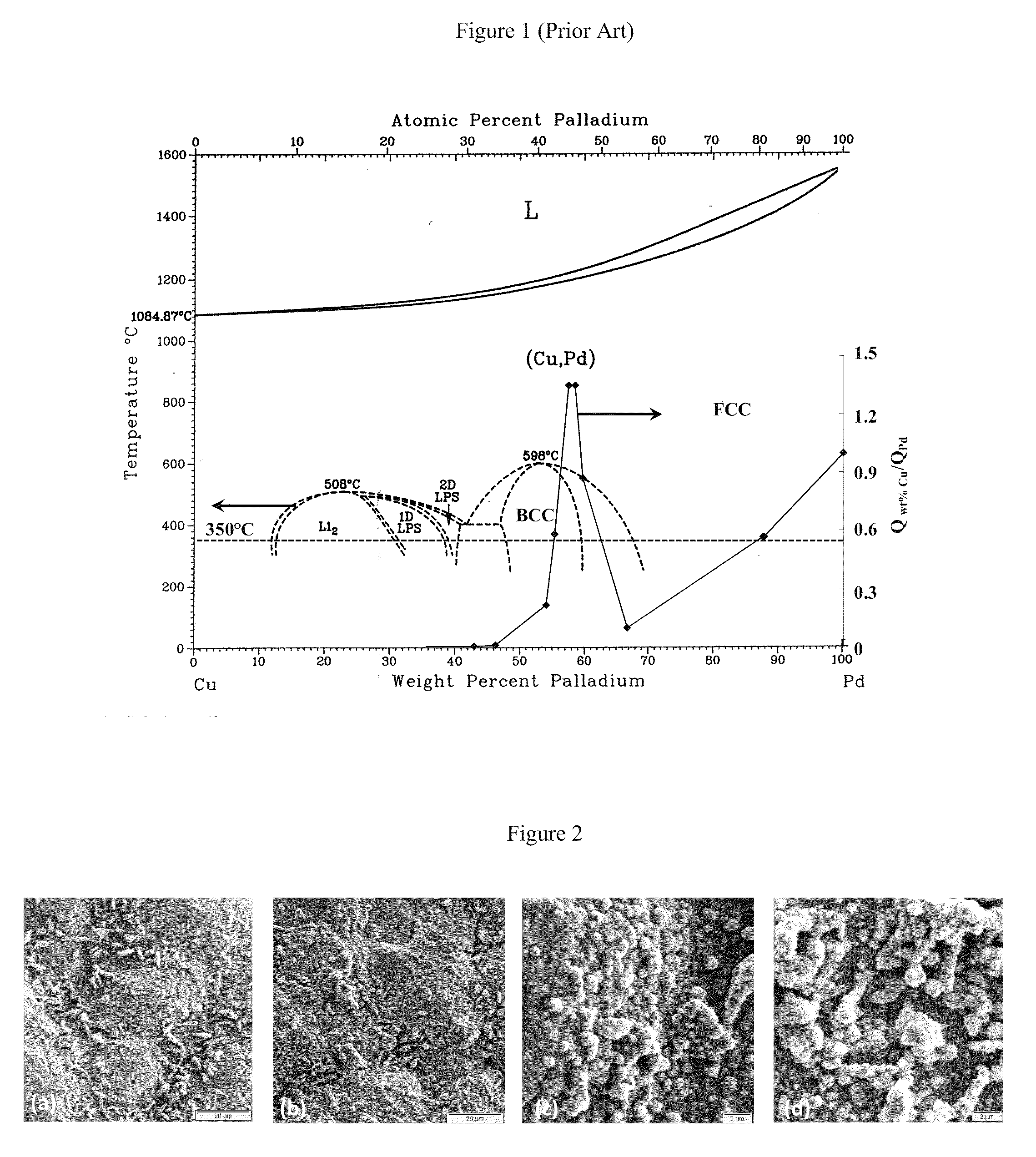
TABLE 1Plating and galvanic displacement bath compositions and conditionsPd galvanicStandardDilute CudisplacementPd bathCu bathbathbathPd(NH3)4Cl2•H2O (g / l)4CuSO4•5H2O (g / l)252.5PdCl2 (g / l)1.0Na2EDTA•2H2O (g / l)40.147.54.75NH4OH (28%) (ml / l)198H2NNH2 (98%) (ml / l)0.19H2CO (37%) (ml / l)252.5EDA (ppm)11211.2K4Fe(CN)6•3H2O (ppm)353.5(C2H5)2NCS2Na•3H2O50.5(ppm)pH10-1112.012.72Temperature (° C.)6020-2520-2520-25

[0045]After the Cu plating solution was prepared and the pH adjusted by adding concentrated NaOH or KOH solution, the activated support was immersed for 10-60 minutes at room temperature, depending on the desired thickness. After plating Cu, the supports were immediately immersed in 0.01 M HCl to neutralize any residual plating ...

example 3

Galvanic Displacement of Cu by Pd

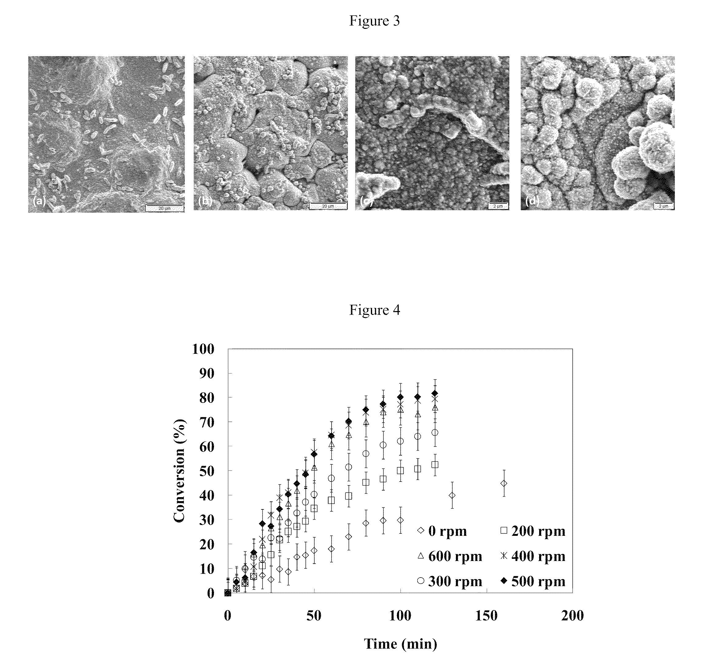
[0056]In order to form the Pd / Cu / Pd tri-layer, a galvanic displacement step was performed. During the galvanic displacement step, Pd is deposited while Cu is displaced. The samples were first plated with roughly 1.5 μm of Cu. In order to conduct the galvanic displacement, the samples were immersed in a PdCl2 solution that was agitated at varying speeds for 1.5 hours. The composition of the Pd galvanic displacement bath is described in Table 1. The galvanic displacement of Cu occurs according to the following electrochemical reaction where the Pd2+ ion in solution replaces the Cu metal on the substrate:

Pd2++2e-→Pd0E0=0.951V+Cu2++2e-→Cu0E0=0.3419VPd2++Cu0→Pd0+Cu2+E0=0.6091V

[0057]FIG. 6 is a secondary electron imaging (SEI) surface micrograph at 3000× of samples plated with Cu and further displaced by Pd with (a) an unagitated bath, and with a bath agitated at speeds of (b) 200 rpm, (c) 400 rpm, and (d) 600 rpm. For the images shown in FIG. 6, the sampl...


PUM

PropertyMeasurementUnit
Temperatureaaaaaaaaaa

Abstract

A method of making a membrane permeable to hydrogen gas (H2↑) is disclosed. The membrane is made by forming a palladium layer, depositing a layer of copper on the palladium layer, and galvanically displacing a portion of the copper with palladium. The membrane has improved resistance to poisoning by H2S compared to a palladium membrane. The membrane also has increased permeance of hydrogen gas compared to palladium-copper alloys. The membrane can be annealed at a lower temperature for a shorter amount of time.

Description

RELATED APPLICATION[0001]This application claims the benefit of U.S. Provisional Application No. 61 / 330,511, filed on May 3, 2010.[0002]The entire teachings of the above application are incorporated herein by reference.GOVERNMENT SUPPORT[0003]This invention was made with government support under grants DE-FC26-07NT43058 and DE-FG26-04NT42194 awarded by the U.S. Department of Energy. The government has certain rights in the invention.BACKGROUND OF THE INVENTION[0004]The recent international concern regarding the climate change has prompted carbon cap and trade agreements and sparked interest in emission free energy productions. In addition to its many uses in the chemical and petrochemical industries, hydrogen has the potential of being a sustainable “emissions free” energy carrier. Steam reforming and coal gasification, which are already common industrial processes, can be coupled with CO2 capture and sequestration as a means of producing hydrogen on an industrial scale with limited...

Claims


Application Information

Patent Timeline
IPC IPC(8): C25D5/50B01D71/02B01D53/22
CPCB01D67/0069B01D2325/04B01D69/12B01D71/022C01B3/505C01B2203/0405C23C18/165C23C18/1651C23C18/1831C23C18/405C23C18/54B01D67/0093B01D2323/08B01D2325/023B01D69/105
Inventor MA, YI HUAPOMERANTZ, NATALIE
Owner WORCESTER POLYTECHNIC INSTITUTE
Why Eureka
Try Eureka