Mobile figure stand

a technology for figures and stands, applied in the field of stands, can solve problems such as creating sporadic and unpredictable movement patterns, and achieve the effect of facilitating vertical adjustment and horizontal adjustmen

Inactive Publication Date: 2011-12-15
SAMARAS GREGORY +1
View PDF9 Cites 11 Cited by
  • Summary
  • Abstract
  • Description
  • Claims
  • Application Information

AI Technical Summary

Benefits of technology

[0004]A mobile figure stand includes a horizontal frame and a vertical stake where the frame moves in response to environmental cues such as air force, varying strengths of wind energy or manual force. In one embodiment, the stake may include an outer and inner post. The outer and inner posts are coupled by mechanisms such as a pin-hole or a friction-fit mechanism. In one embodiment, the stake may facilitate vertical adjustment of the stand and thus the horizontal frame at any distance from the ground. A bottom end of the vertical stake may be inserted into the ground or into a base. The top end of the vertical stake is inserted through a central port of the horizontal frame. A fastener or tension adjuster is placed at the junction by the vertical stake and the central horizontal frame and is used to manage the rotational speed of the horizontal frame and may be used to facilitate vertical adjustment of the horizontal frame from the ground. When tension is applied to the central horizontal frame by the tension adjuster fastener, the rotational speed of the central horizontal frame slows down and when less or no tension is applied the central horizontal frame is permitted to freely rotate about 360 degrees clockwise or counterclockwise or in a random rotational manner.
[0005]The horizontal frame further includes two horizontal extension frames and two vertical support rods. The inner ends of the horizontal extension frames are connected to the central horizontal frame and the outer ends of the horizontal extension frames are connected to vertical support rods. The vertical support rods hold figures such as animal decoys or seasonal figurines which are designed to capture wind energy or wind force. The wind force propels the figures to rotate about the vertical support rods and also permits circular rotation of the frame about the stake of the stand. In addition to this movement pattern the winds velocity and direction often varies allowing each of the decoy figures to compensate for the others movement. This check and balance system discourages a merry-go-round effect and instead creates a sporadic and unpredictable movement pattern. As the decoys / figures rotate and roam on their individual axis each establish an individual character. The decoys will sometimes come to a complete stop and remain stationary only to change direction and once again continue their irregular maneuvering and alternate direction while traveling about the stake. This unpatterned, irregular maneuvering creates a non-repetitious sequence and life-like display.

Problems solved by technology

This check and balance system discourages a merry-go-round effect and instead creates a sporadic and unpredictable movement pattern.

Method used


Image

  • Mobile figure stand
  • Mobile figure stand
  • Mobile figure stand

Examples


Embodiment Construction

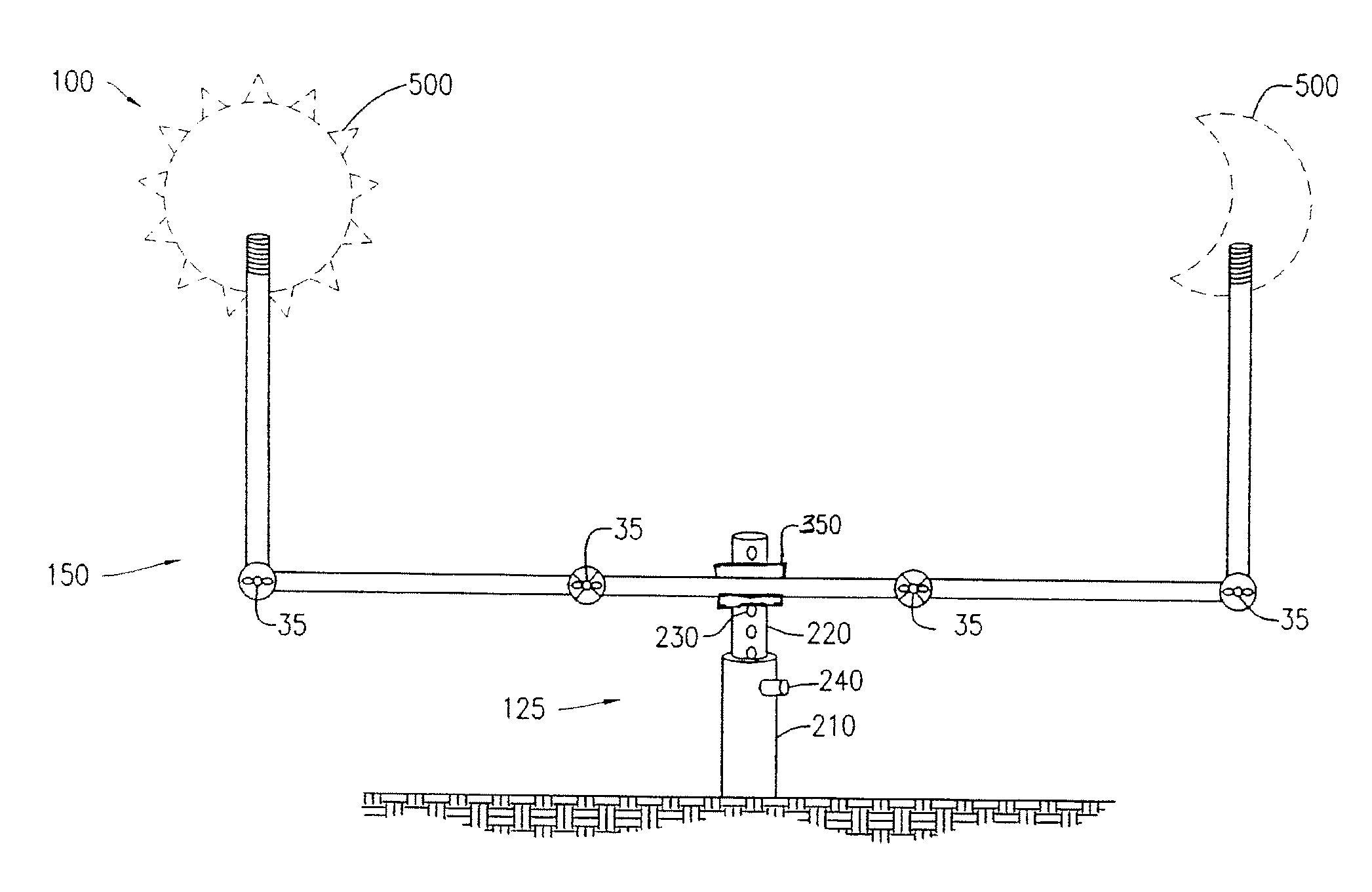
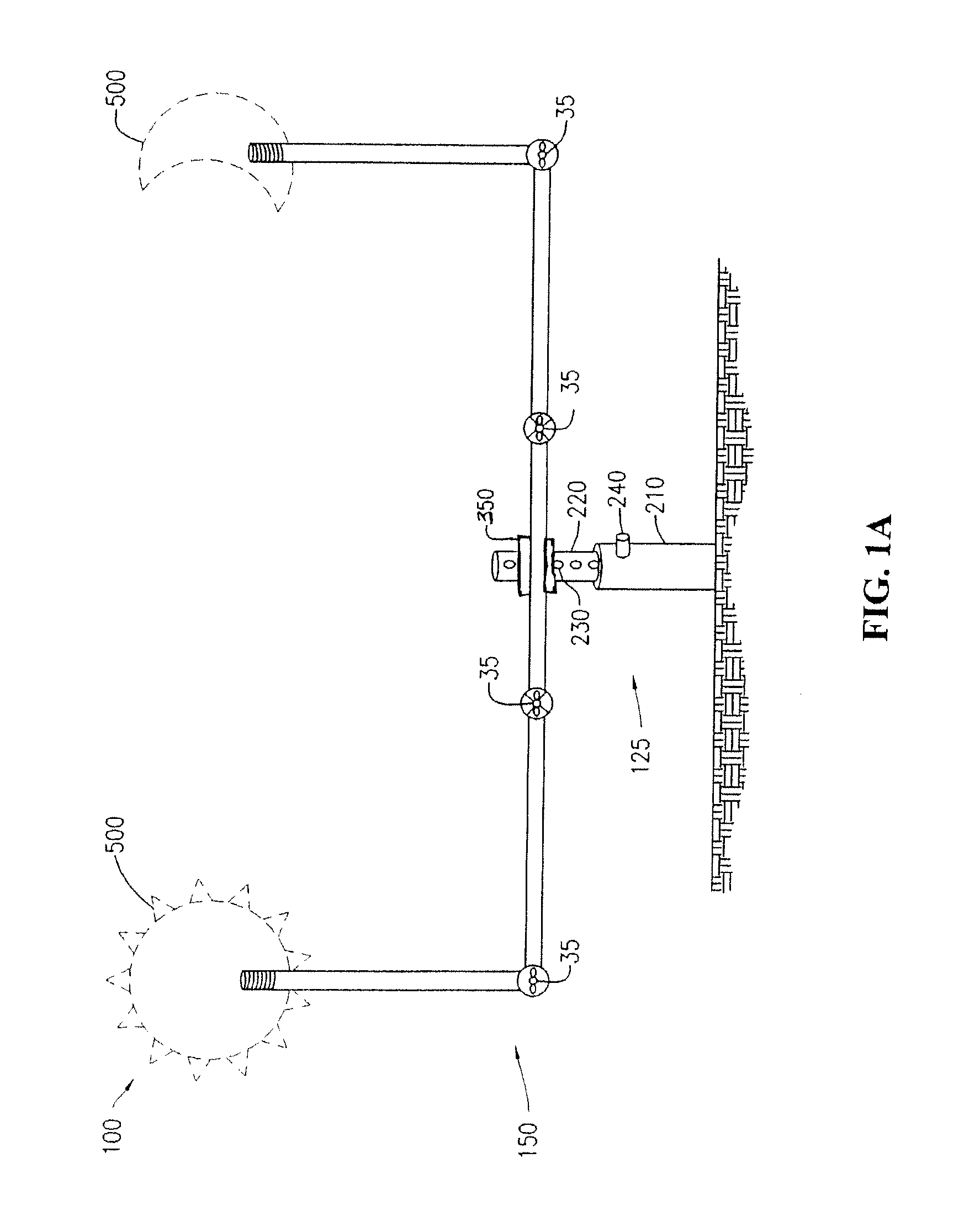
[0013]FIG. 1A shows a mobile figure stand 100. The stand 100 includes a vertical stake 125 and a horizontal frame 150. The stake 125 has a top end that inserts into the frame 150 and a bottom end for inserting into the ground or other surface. The vertical stake 125 includes a height adjusting mechanism that permits the frame 150 to be adjusted to any distance from the ground or support surface. In one embodiment, the stake 125 includes an outer post 210 coupled to an inner post 220. The outer and inner posts 210, 220 are part of the height adjusting mechanism wherein the outer and inner posts 210, 220 are coupled together to permit the raising and lowering of the frame 150 that is attached to the stake 125. The outer and inner posts 210, 220 may be coupled together using any number of mechanisms such as by friction fit, hole 230 and pin 240, screw groves, clamps, pneumatic systems, etc. In one preferred embodiment any simple height adjusting mechanism is used.

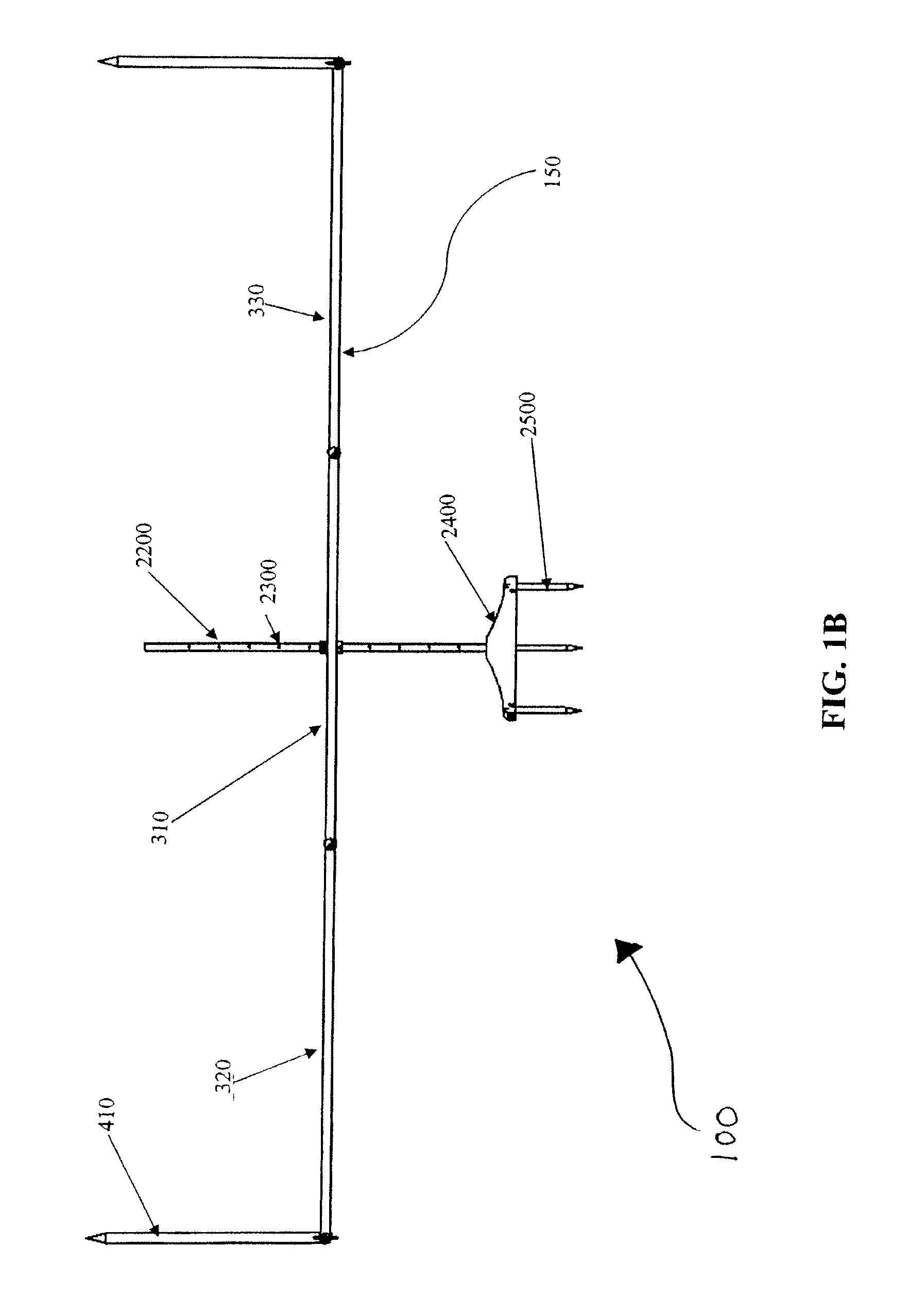
[0014]FIG. 1B shows an...


PUM


Abstract

A decoy display stand powered by air flow or wind force is provided including a vertical stake and a horizontal frame. The frame includes vertical support rods and a horizontal bar having a central horizontal frame and two horizontal extension frames. The vertical support rods are disposed at the outer ends of the horizontal extension frames and receive figures such as animal decoys or seasonal ornaments. The stake is received by the central horizontal frame and permits 360 degree rotation of the central horizontal frame around the stake with wind or manual energy. The figures are designed to capture energy and facilitate the rotation of the frame about the stake. A fastener is provided adjacent the central horizontal frame and the stake to manage rotation of the frame in varying degrees between free rotation and no rotation and, in some cases, adjust the height of the frame from the ground.

Description

PRIORITY AND RELATED APPLICATION[0001]This application claims priority to U.S. Provisional Patent Application Ser. No. 61 / 354,796, filed Jun. 15, 2010, entitled DECOY DISPLAY, which is hereby incorporated by reference in its entirety.FIELD OF THE INVENTION[0002]The present invention relates to stands for holding ornamental figures or decoys, particularly to portable stands that both support and permit movement of ornamental figures or decoys by wind, energy or air force.BACKGROUND OF THE INVENTION[0003]Outdoor support stands for decoys or lawn ornaments exists, however none provide the ability to freely rotate in at least two points in response to environmental cues such as wind, energy or air force. This is especially true with hunting decoys displays. One hunting decoy display stand that is deficient is U.S. Pat. No. 7,788,840 to Wyant, et al. The '840 patent provides an apparatus for revolving decoys about a vertical axis using a motor and a complex support structure. Rotation is...

Claims


Application Information

Patent Timeline
Patent Type & Authority Applications(United States)
IPC IPC(8): F16M11/20
CPCA01M31/06F16M11/24G09F15/0087F16M13/022G09F7/22F16M11/38
Inventor SAMARAS, GREGORYBOLL, EDWARD J.
Owner SAMARAS GREGORY
Why Eureka
Try Eureka