
Wind Turbine Nacelle, Transport System for a Wind Turbine Nacelle and Method for Transporting a Wind Turbine Nacelle

a technology for wind turbines and nacelles, which is applied in the direction of transportation items, vehicle transportation, vehicle carrying long loads, etc., can solve the problems of dangerous nacelles and turbine nacelles, and achieve the effects of reducing height, high stability, and preparing for the transport of such nacelles

Active Publication Date: 2011-12-15
SIEMENS GAMESA RENEWABLE ENERGY AS
View PDF2 Cites 5 Cited by
  • Summary
  • Abstract
  • Description
  • Claims
  • Application Information

AI Technical Summary

Benefits of technology

[0008]It is therefore the object of the invention to provide the possibility for a wind turbine nacelle to be transported and / or to be supplied for transport in a way that best suits both the circumstances of transport, in particular the height limits, and at the same time makes such transport safer for the wind turbine nacelle itself.
[0032]In a preferred embodiment of the transport system the bridge assembly comprises several separate construction parts (such as the longitudinal beams and the cross beam) which are detachably interconnected in an assembled state. This way the construction parts can be assembled around the nacelle and dense to leg arrangements. This means that the nacelle with its leg arrangements does not need to be lifted onto the bridge arrangement, but rather the bridge arrangement is built around it. This results in a reduction of effort and costs.

Problems solved by technology

This is a problem for wind turbine nacelles in particular.
Therefore, the same forces might not seriously affect a tower segment while they might be quite dangerous to a nacelle.

Method used


Image

  • Wind Turbine Nacelle, Transport System for a Wind Turbine Nacelle and Method for Transporting a Wind Turbine Nacelle
  • Wind Turbine Nacelle, Transport System for a Wind Turbine Nacelle and Method for Transporting a Wind Turbine Nacelle
  • Wind Turbine Nacelle, Transport System for a Wind Turbine Nacelle and Method for Transporting a Wind Turbine Nacelle

Examples


Embodiment Construction

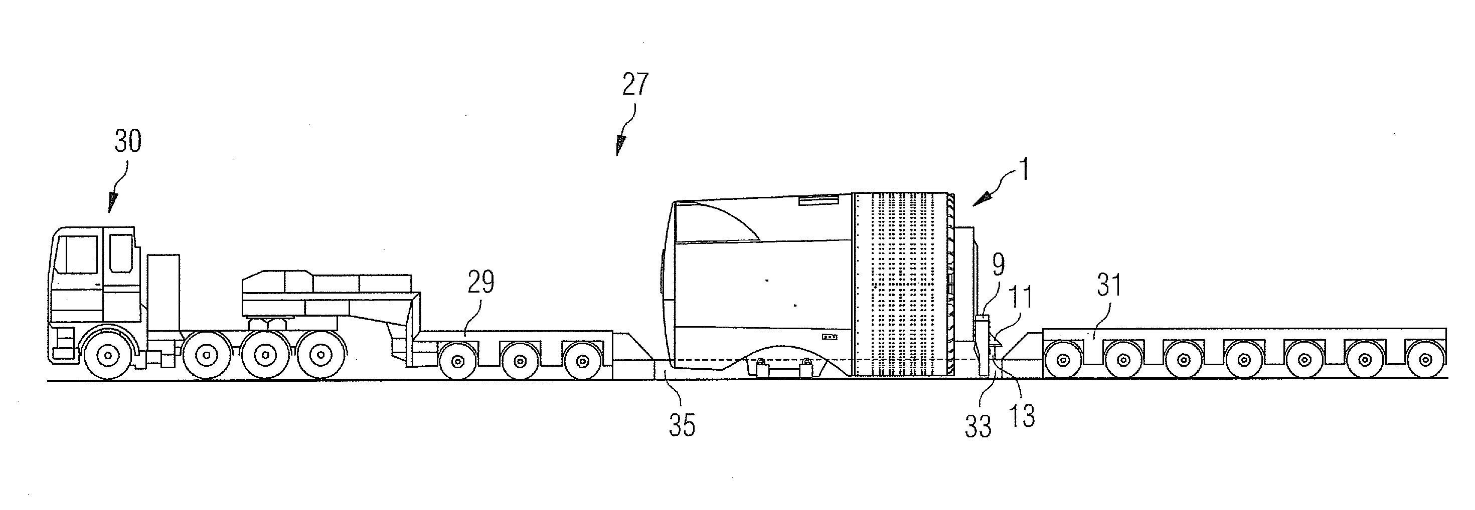
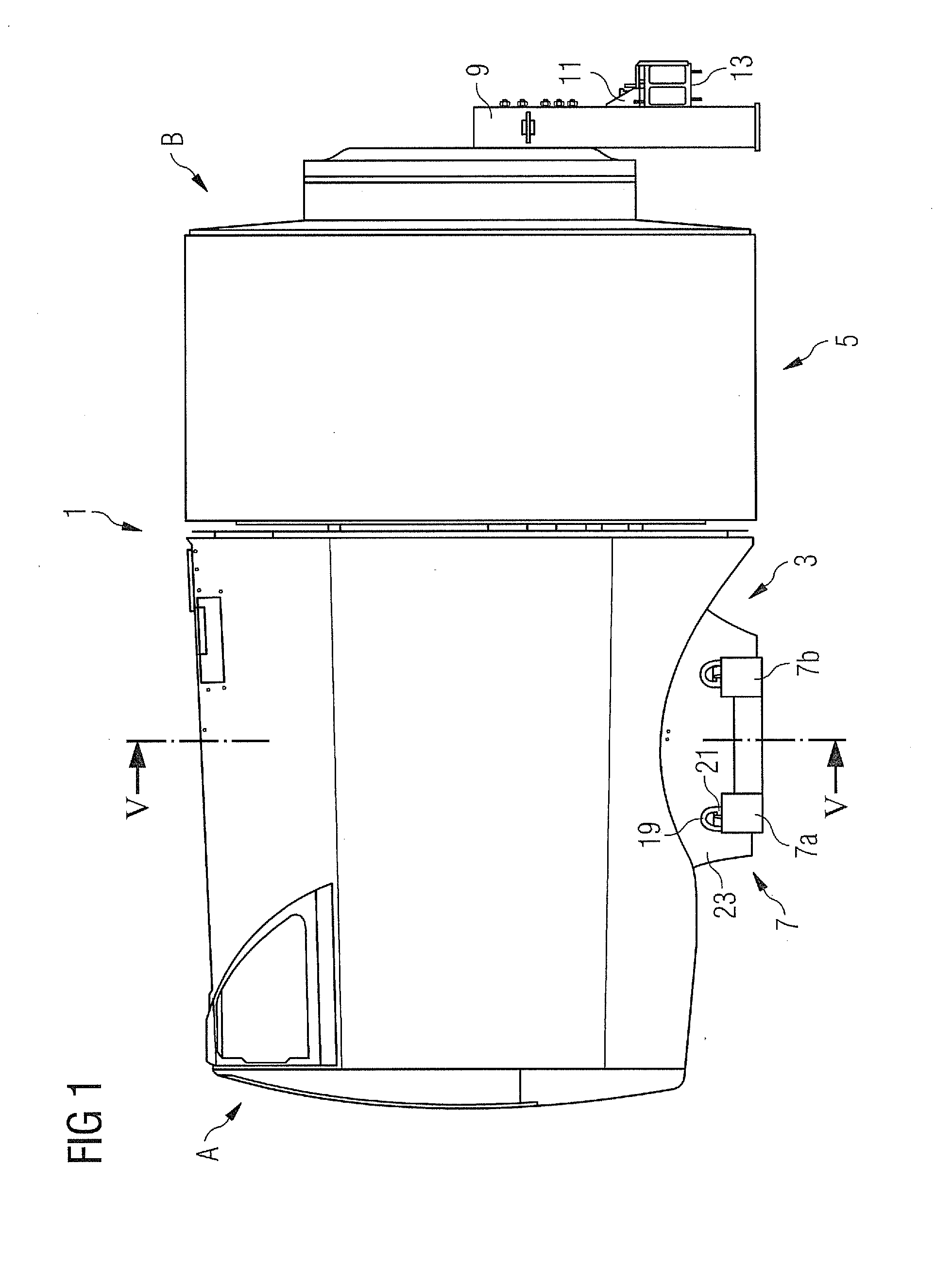
[0046]FIGS. 1 to 5 show a wind turbine nacelle 1. Referring in particular to FIG. 1, the nacelle 1 has a longitudinal extension with a front end B and a rear end A. The nacelle 1 has a bottom part 5 in which there is an opening 3. A first leg arrangement 9 is attached at the front end B of the nacelle 1 and a second leg arrangement 7 is attached at the bottom part 5. More specifically, the second leg arrangement 7 is inserted into the opening 3.

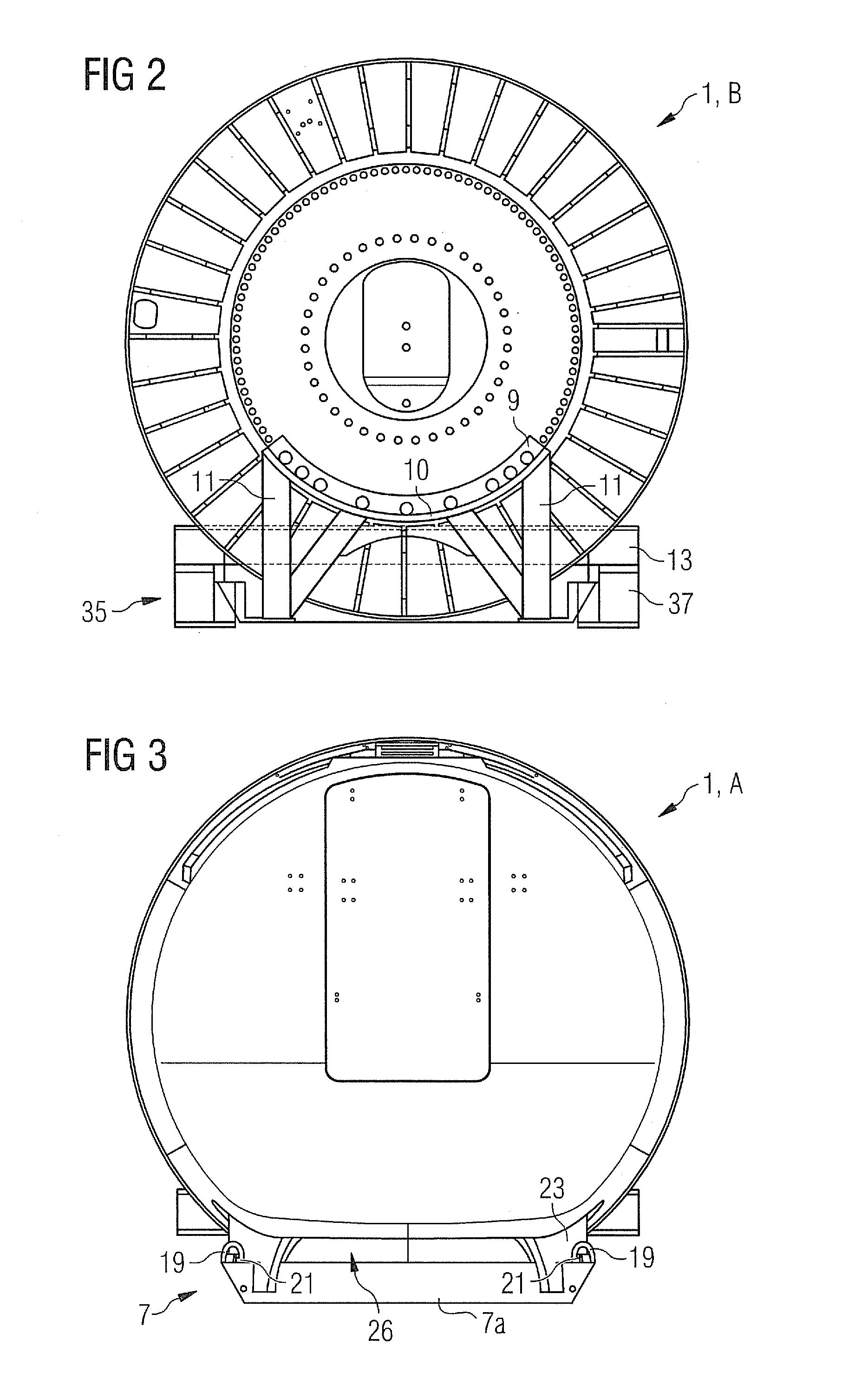
[0047]The leg arrangement 9 is bolted to the front end B of the nacelle 1, i.e. in a region in which the hub of the rotor (not shown) of the wind turbine will be fixed later. The leg arrangement 9 (cf. FIG. 2) comprises two legs which end in a semi circular carrier structure 10. In the region of the carrier structure 10 the leg arrangement 9 is bolted temporarily to the front end B of the nacelle 1. The leg arrangement 9 has a main vertical extension. However, at the side facing away from the front end B off the nacelle 1 there is attached a ...


PUM

PropertyMeasurementUnit
diameteraaaaaaaaaa
forceaaaaaaaaaa
sizeaaaaaaaaaa

Abstract

A wind turbine nacelle is provided. The wind turbine nacelle includes a longitudinal extension and a bottom part. The longitudinal extension has a rear end and a front end. At the bottom part, an opening is located which serves as an interface to a tower of a wind turbine at a designated assembly situation of the nacelle. A first detachable leg arrangement is attached to at least one of the front end and the rear end. A second detachable leg arrangement is attached at the bottom part. Further embodiments are directed to a transport system for a wind turbine nacelle and to a method for transporting a wind turbine nacelle.

Description

CROSS REFERENCE TO RELATED APPLICATIONS[0001]This application claims priority of European Patent Office application No. 10165733.6 EP filed Jun. 11, 2010, which is incorporated by reference herein in its entirety.FIELD OF INVENTION[0002]The present invention concerns a wind turbine nacelle with a longitudinal extension with a rear end and a front end and with a bottom part at which there is located an opening serving at a designated assembly situation of the nacelle to be an interface to a tower of a wind turbine. It also concerns a transport system for a wind turbine nacelle and a method of transporting such wind turbine nacelle.BACKGROUND OF INVENTION[0003]The transport of large wind turbine components such as nacelles or tower segments by lorry or other earth-bound vehicles is usually quite complicated. Due to the large load, in particular the weight of such wind turbine components, it is usually necessary to use cranes in order to load or unload large wind turbine components ont...

Claims


Application Information

Patent Timeline
Patent Type & Authority Applications(United States)
IPC IPC(8): F03D11/04B60P3/40B23P11/00B62D53/00
CPCB60P3/40F03D1/005Y10T29/49826Y02E10/726Y02E10/722F03D11/00F03D13/40F03D80/00Y02E10/72B62D53/00
Inventor POULSEN, HENNING
Owner SIEMENS GAMESA RENEWABLE ENERGY AS
Learn More