
Adaptive Beamforming

a beamforming and beam technology, applied in the field of wireless communication, can solve the problems of limiting the direct applicability of channel estimation in its current form, high penetration loss, and not always being able to exchange a known set of training symbols between the tx and rx antenna elements, so as to improve the robustness of calibration errors, reduce complexity, and increase speed

Inactive Publication Date: 2011-12-15
NEC LAB AMERICA
View PDF13 Cites 9 Cited by
  • Summary
  • Abstract
  • Description
  • Claims
  • Application Information

AI Technical Summary

Benefits of technology

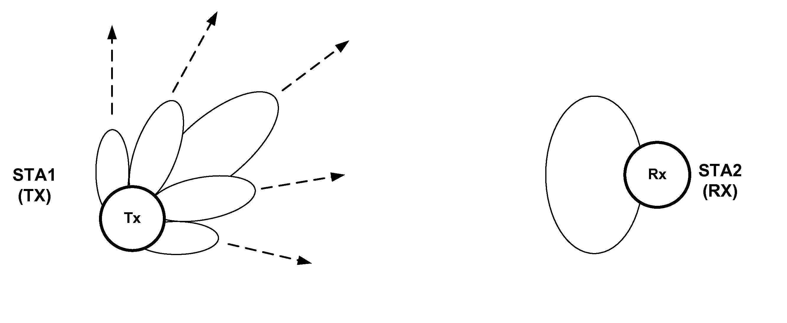
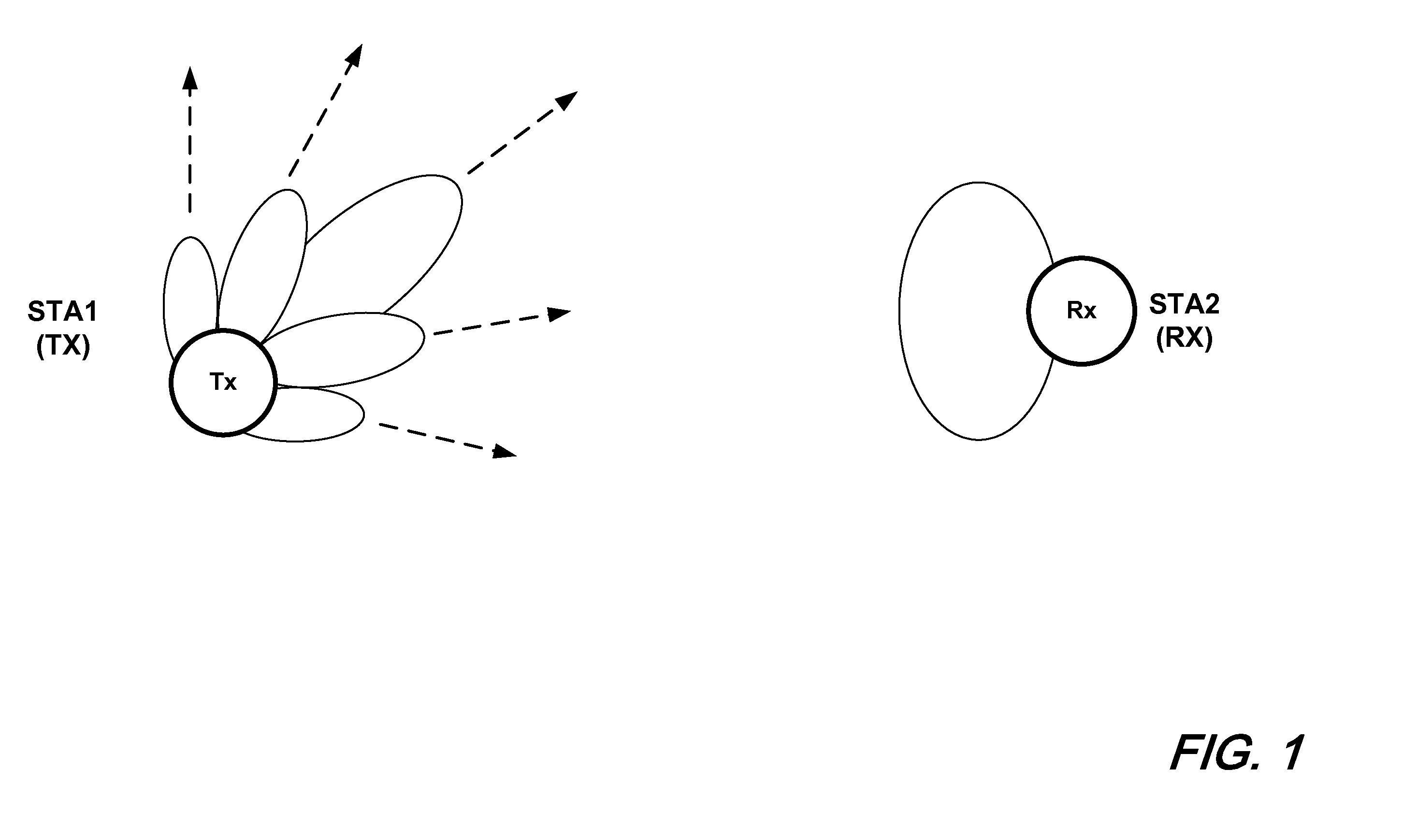
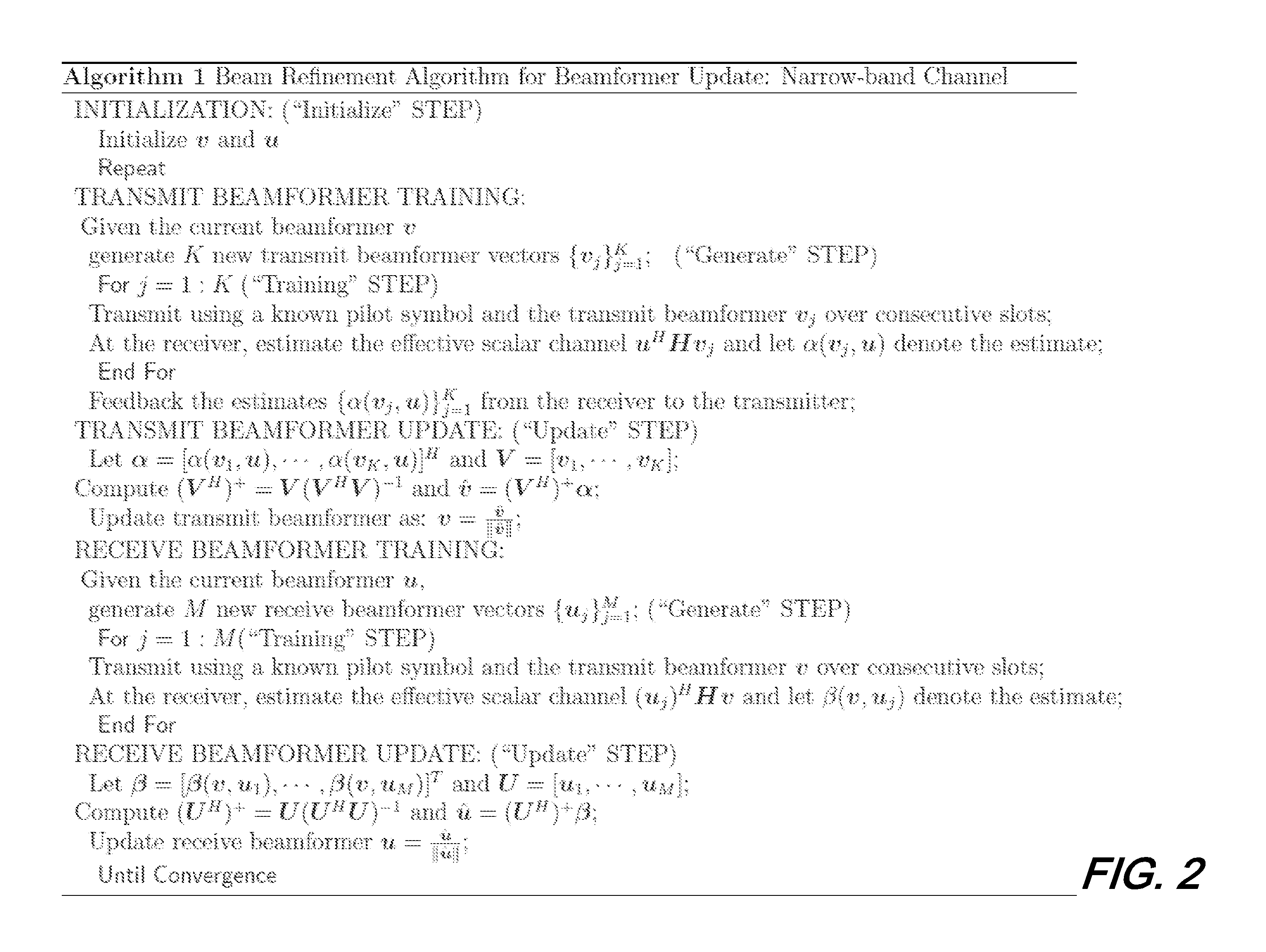
[0009]More particularly, a method of the instant disclosure is an iterative one that uses feedback about amplitude and phase of the effective scalar channel gain. The iterative method is advantageously able to quickly converge on the transmit and / or receive antenna weight vector. In a preferred operation, the method is robust to calibration errors as a transmit sector that is used as a starting point for transmit beamforming may advantageously be used as a starting point for receive beamforming. Such operation offers considerable advantage over prior art methods as the determination of a starting point for receive beamforming is frequently time consuming since—in prior art methods—it typically involves slowly sweeping across all sectors as part of an initial acquisition. Additionally, methods according to the present disclosure may work with antenna weight vectors which may be generated at runtime—in addition to those comprising the codebook.
[0011]Advantageously, methods according to the present disclosure exhibit reduced complexity in that explicit channel estimation is not employed, improved robustness to calibration errors, increased speed, and enhanced accuracy.

Problems solved by technology

With 60 GHz radios however, two issues limit the direct applicability of channel estimation in its current form.
First, it may not always be possible to exchange a known set of training symbols between the TX and RX antenna element due to the increased signal attenuation caused by (a) the small size (small aperture area) of the antenna elements, and (b) high penetration loss due to link blockage.
In many cases, a transmit and receive antenna element pair may not be able to communicate at all.
Second, the typical use of a large number of antenna elements with these radios implies that even when all elements can communicate with each other, explicit channel estimation may not be practically feasible due to the time taken or the energy consumed.

Method used


Image

  • Adaptive Beamforming
  • Adaptive Beamforming
  • Adaptive Beamforming

Examples


Embodiment Construction

[0016]The following merely illustrates the principles of the various embodiments. It will thus be appreciated that those skilled in the art will be able to devise various arrangements which, although not explicitly described or shown herein, embody the principles of the embodiments and are included within their spirit and scope.

[0017]Furthermore, all examples and conditional language recited herein are principally intended expressly to be only for pedagogical purposes to aid the reader in understanding the principles of the embodiments and the concepts contributed by the inventor(s) to furthering the art, and are to be construed as being without limitation to such specifically recited examples and conditions.

[0018]Moreover, all statements herein reciting principles, aspects, and embodiments of the invention, as well as specific examples thereof, are intended to encompass both structural and functional equivalents thereof. Additionally, it is intended that such equivalents include bo...


PUM


Abstract

A computer implemented method for generating transmit (TX) and receive (RX) antenna weight vectors (AWVs) for beamforming without utilizing explicit channel estimation.

Description

CROSS REFERENCE TO RELATED APPLICATION[0001]This application claims the benefit of U.S. Provisional Patent Application Ser. No. 61 / 353,436 filed Jun. 10, 2010 the entire file wrapper of which is incorporated by reference as if set forth at length herein.FIELD OF DISCLOSURE[0002]This disclosure relates to the field wireless communications and in particular to an adaptive beamforming method for 60 GHz wireless communication devices without explicit channel estimation.BACKGROUND OF DISCLOSURE[0003]As may be appreciated by those skilled in the art, beamforming is an attractive technique to improve 60 GHz wireless communications due—in part—to its unique combination of high free space path loss and the potential for increased antenna directivity. As is known, beamforming (i.e. adaptive beamforming) involves dynamically changing beams or antenna patterns in signal space to maximize channel gain and minimize interference. Those skilled in the art will recognize that this is different, and ...

Claims


Application Information

Patent Timeline
Patent Type & Authority Applications(United States)
IPC IPC(8): H01Q3/00
CPCH01Q3/2605H04B7/063H04B7/0617
Inventor PRASAD, NARAYANRAMACHANDRAN, KISHORERANGARAJAN, SAMPATH
Owner NEC LAB AMERICA
Learn More