Portable cutting machine

a cutting machine and portability technology, applied in metal sawing accessories, manufacturing tools, metal sawing devices, etc., can solve problems such as difficulty in fatigue of operators, and achieve the effect of improving operability and improving work safety

Inactive Publication Date: 2011-12-22
MAX CO LTD
View PDF44 Cites 4 Cited by
  • Summary
  • Abstract
  • Description
  • Claims
  • Application Information

AI Technical Summary

Benefits of technology

According to the portable cutting machine having the above structure, since the adjusting lever of the cutting-depth adjusting mechanism is arranged between the battery pack and the saw blade, the adjusting lever can be arranged in the back position of the cutting machine main body almost similarly to the conventional adjusting lever. Therefore, without operator's confusion, operability is not damaged. Further, since an accident that the adjusting lever bumps against other members during the cutting operation becomes difficult to occur, malfunction of the cutting-depth adjusting mechanism is hardly produced, so that safety of the work is improved. Further, since the adjusting lever is formed in the turning shape to the backside of the saw cover, the operability is improved.

Problems solved by technology

Hereby, since right-left balance in weight is good when an operator holds the portable cutting machine in his hand, and the portable cutting machine is stable without tilting neither to the left nor to the right, the portable cutting machine is good in handling and the operator is difficult to get tired even if he uses the portable cutting machine for a long time.

Method used


Image

  • Portable cutting machine
  • Portable cutting machine
  • Portable cutting machine

Examples


Embodiment Construction

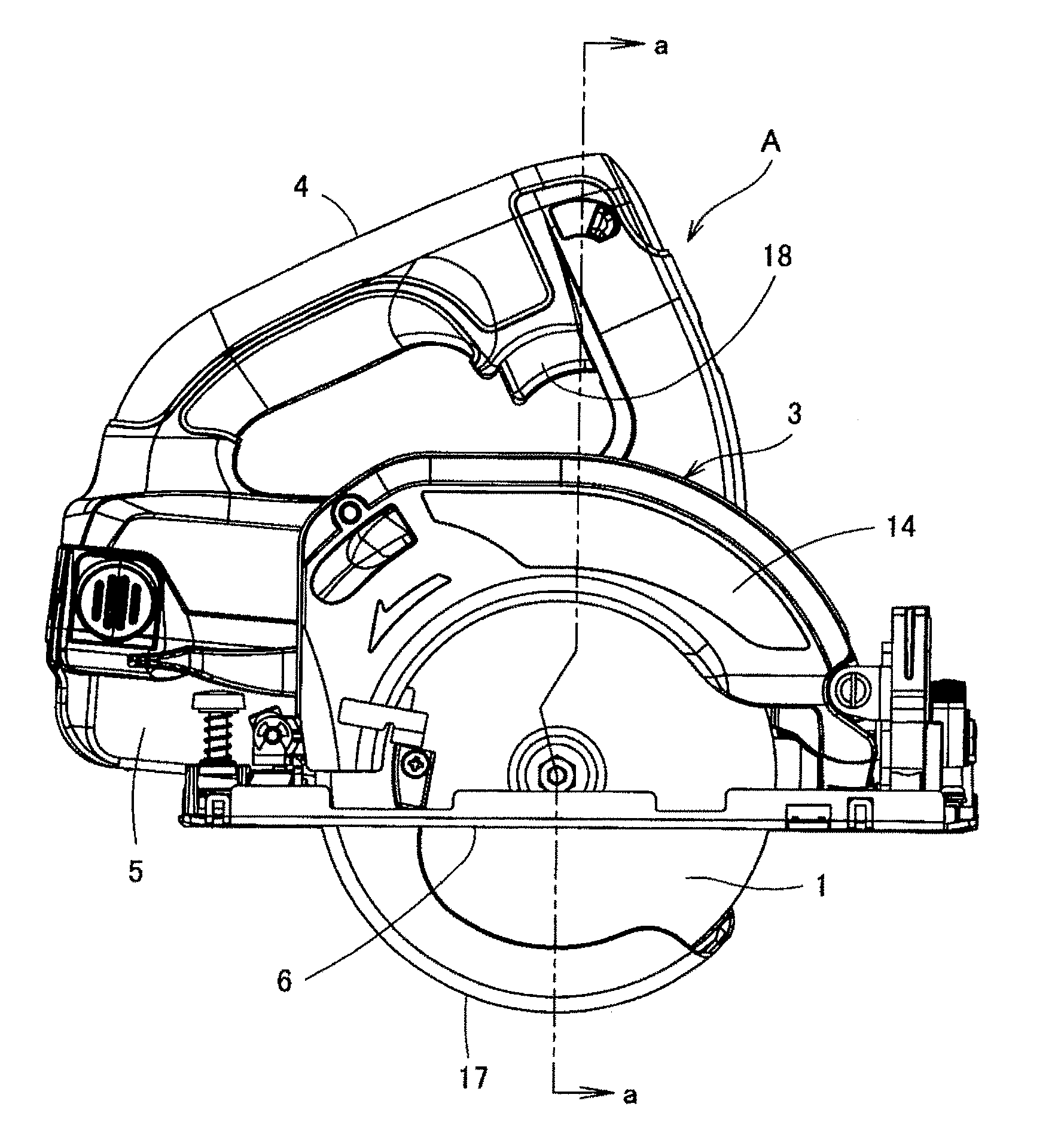
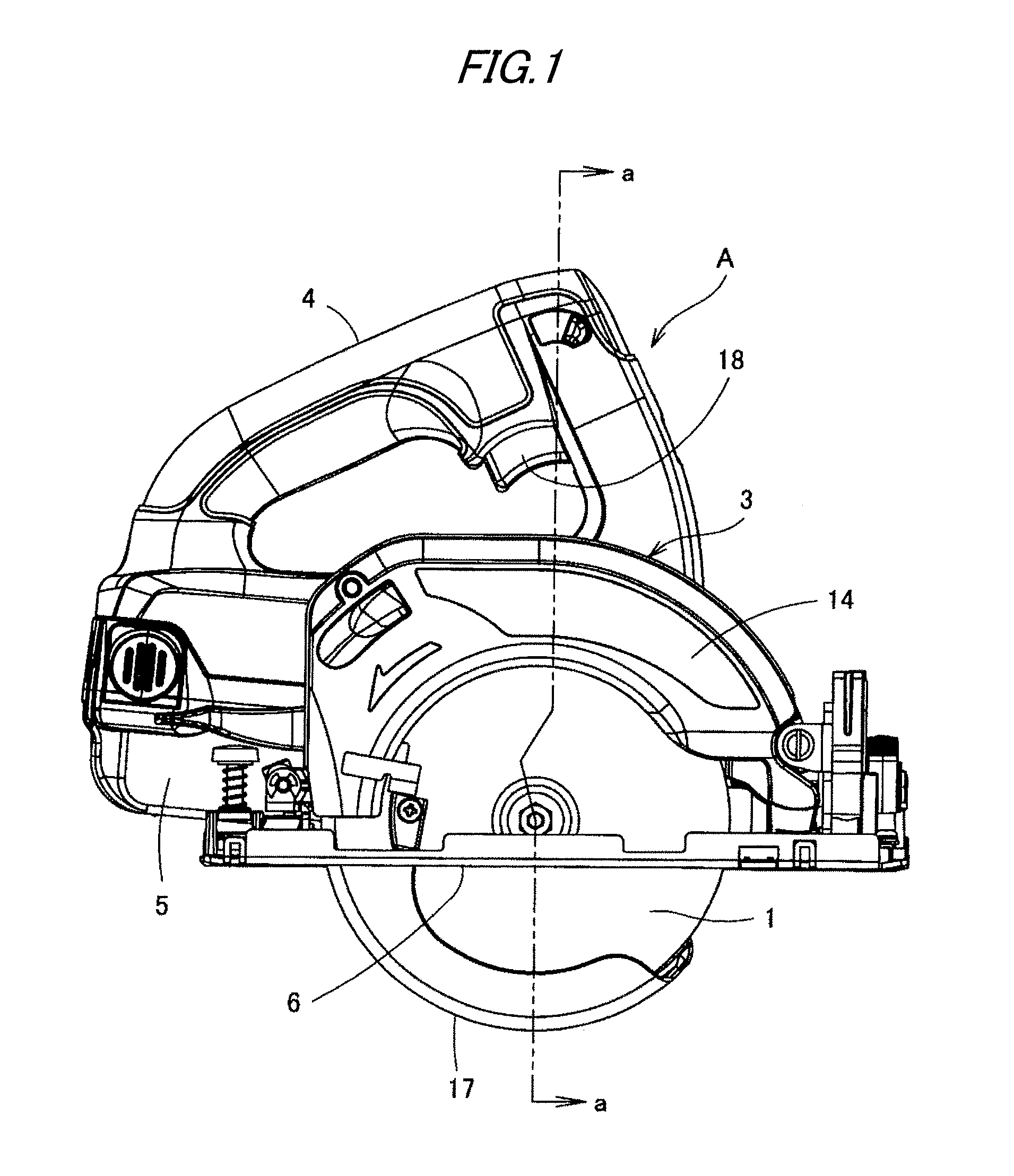
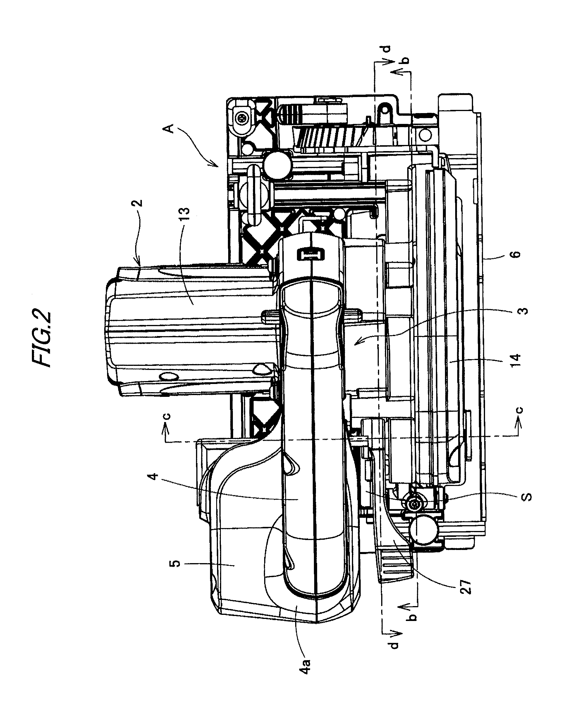
In FIGS. 1 to 3, a reference character “A” represents a portable cutting machine according to an exemplary embodiment of the invention. In the cutting machine, a saw blade (circular saw) 1 and an electric motor 2 for driving this saw blade 1 are provided on a cutting machine main body 3 side by side in the right-left direction. The saw blade 1 is rotatably provided on the cutting machine main body 3. On top of the cutting machine main body 3, a handle 4 for operation is arranged in parallel to a cutting direction of the saw blade 1, that is, in a front-back direction. Namely, the handle 4 is provided, in a first direction parallel to a rotation shaft 9 of the saw blade 1, between the saw blade 1 and the electric motor 2, and extends in a second direction perpendicular to the first direction. To a lower portion of a rear end 4a of the above handle 4, a battery pack 5 for driving the electric motor 2 is provided detachably. At the bottom of the cutting machine main body 3, there is pr...


PUM

PropertyMeasurementUnit
angleaaaaaaaaaa
weight balanceaaaaaaaaaa
weightaaaaaaaaaa

Abstract

A portable cutting machine is provided with: a cutting machine main body (3); a saw blade (1) provided rotatably with respect to the cutting machine main body (3); an electric motor (2) adapted to drive the saw blade (1); a handle (4) which is provided between the saw blade (1) and the electric motor (2) in a first direction parallel to a rotation shaft (9) of the saw blade (1) and extends in a second direction perpendicular to the first direction; a battery pack (5) adapted to drive the electric motor (2); and a surface plate (6) rotatably supported by the cutting machine main body (3). A center in the first direction of the battery pack (5) is located closer to a side of the electric motor (2) than a center in the first direction of the handle (4). The rotation shaft (9) of the saw blade (1) is located on one side of the surface plate (6). A part of the saw blade (1) passes through an opening portion (16) penetrating through the surface plate (6) and is exposed to the other side of the surface plate (6). A projecting amount of the saw blade (1) by which the part of the saw blade (1) projects from the other side of the surface plate (6) is changeable by changing an angle of the surface plate (6) with respect to the cutting machine main body (3). A cutting-depth adjusting mechanism adapted to change the angle of the surface plate (6) with respect to the cutting machine main body (3) is located, in the first direction, closer to a side of the saw blade (1) than the battery pack (5).

Description

TECHNICAL FIELDThe present invention relates to a portable cutting machine driven by a battery.BACKGROUND ART It has been a mainstream to use a home commercial power supply for this type of portable cutting machine. However, in such the portable cutting machine, there are problems that a power cable tags along thereby to cause bad handling of the cable, and utilization is not permitted when there is no power supply close. Therefore, recently, a machine provided with a battery pack which can be detachably attached as a power supply has been offered in markets (refer to Patent Documents 1, 2, and 3).PRIOR ART DOCUMENTPatent DocumentPatent Document 1: JP-2008-018498-APatent Document 2: JP-2001-293672-APatent Document 3: JP-2002-316302-AIn such the portable cutting machine, a saw blade, a saw cover for covering the saw blade, and an electric motor for driving the saw blade are provided in a cutting machine main body by side in right-left direction. On top of the cutting machine main bod...

Claims


Application Information

Patent Timeline
Patent Type & Authority Applications(United States)
IPC IPC(8): B23D47/00B23D45/16
CPCB27B9/02B27B9/00
Inventor YOSHIMURA, KAZUNOBUICHIBA, TOMOFUMINONAKA, TAKUMAOKADA, ATSUHITO
Owner MAX CO LTD
Why Eureka
Try Eureka