Phase locked loop

Active Publication Date: 2011-12-22
SK HYNIX INC
View PDF10 Cites 5 Cited by
  • Summary
  • Abstract
  • Description
  • Claims
  • Application Information

AI Technical Summary

Benefits of technology

[0023]Exemplary embodiments of the present invention are directed to reducing the locking time of a phase locked loop.

Problems solved by technology

As a frequency of a system becomes higher, more power may be consumed in the system.
Such physical methods, however, may require additional expenses.
Since systems have been designed not to have a fixed operation frequency but to have varying diverse operation frequencies, the locking time of the phase locked loop may be a serious concern.

Method used


Image

  • Phase locked loop
  • Phase locked loop
  • Phase locked loop

Examples


Embodiment Construction

[0035]Exemplary embodiments of the present invention will be described below in more detail with reference to the accompanying drawings. The present invention may, however, be embodied in different forms and should not be construed as limited to the embodiments set forth herein. Rather, these embodiments are provided so that this disclosure will be thorough and complete, and will fully convey the scope of the present invention to those skilled in the art. Throughout the disclosure, like reference numerals refer to like parts throughout the various figures and embodiments of the present invention.

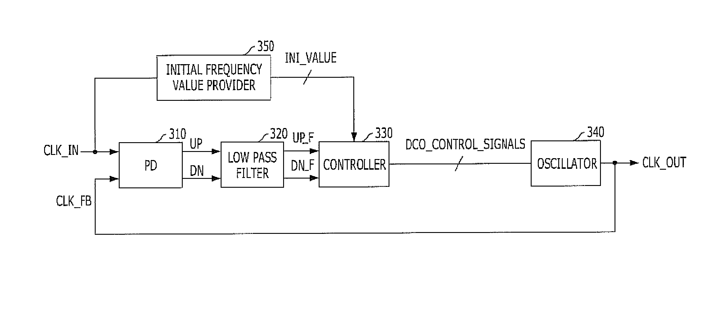
[0036]FIG. 3 is a block view illustrating a phase locked loop in accordance with an exemplary embodiment of the present invention.

[0037]Referring to FIG. 3, the phase locked loop includes a phase detector 310, a controller 330, an oscillator 340, and an initial frequency value provider 350. The phase detector 310 compares the phase of an input clock CLK_IN with the phase of a feedback clock ...


PUM


Abstract

A phase locked loop includes a phase detector configured to compare a phase of an input clock with a phase of a feedback clock to produce a phase comparison result, an initial frequency value provider configured to detect a frequency of the input clock and provide a frequency detection result, a controller configured to generate a frequency control signal based on the phase comparison result and the frequency detection result, and an oscillator configured to generate an output clock in response to the frequency control signal.

Description

CROSS-REFERENCE TO RELATED APPLICATIONS[0001]The present application claims priority of Korean Patent Application No. 10-2010-0058432, filed on Jun. 21, 2010, which is incorporated herein by reference in its entirety.BACKGROUND OF THE INVENTION[0002]Exemplary embodiments of the present invention relate to a technology for reducing locking time of a Phase Locked Loop (PLL).[0003]Technology of generating and using an internal clock is essential to a high-speed synchronous system. Mobile devices have been adopting the high-speed synchronous system as well. As a frequency of a system becomes higher, more power may be consumed in the system. Therefore, technology for reducing power consumption is needed in the system, especially in such mobile devices.[0004]To reduce the amount of power consumption, physical methods such as decreasing parasitic components and lowering the level of power source voltage through micro-processing are used. Such physical methods, however, may require addition...

Claims


Application Information

Patent Timeline
IPC IPC(8): H03L7/08
CPCH03L7/14H03L7/113
Inventor CHOI, HAE-RANGKIM, YONG-JUJANG, JAE-MIN
Owner SK HYNIX INC
Why Eureka
Try Eureka