
System and methods for anatomical structure labeling

Inactive Publication Date: 2011-12-22
CREIGHTON UNIVERSITY
View PDF8 Cites 33 Cited by
  • Summary
  • Abstract
  • Description
  • Claims
  • Application Information

AI Technical Summary

Benefits of technology

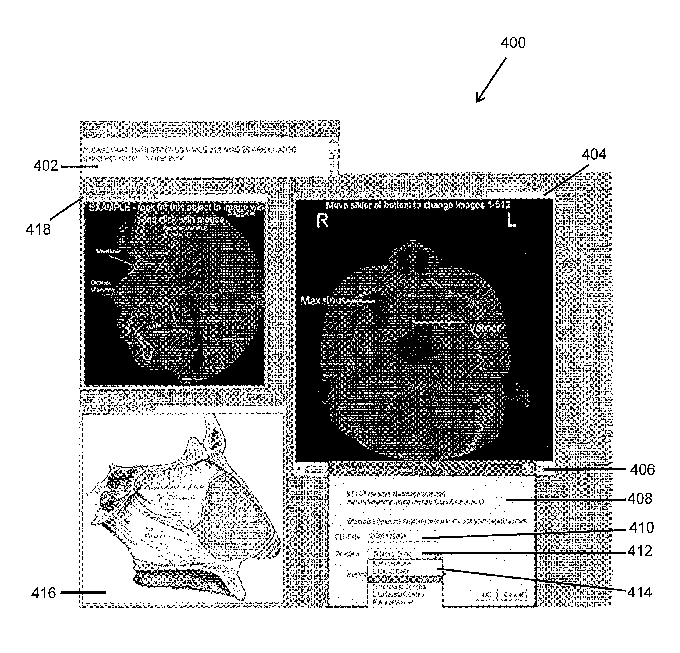
[0011]The system and methods automatically identify anatomical structure. Specifically, anatomical structure is displayed as a closed area on an image slice, otherwise referred to herein as an “anatomical object”. More specifically, when an anatomical object is identified in an image slice, the object is automatically identified in all image slices of the data set. For purposes of this application, image slices are generated by cone beam computed technology (“CBCT”), but any technology for generating image slices is contemplated. An advantage of using CBCT is that up to 512 image slices can be produced in each of the axial, saggital, and coronal planes providing a total of 1,536 image slices f

Problems solved by technology

One difficulty for dentists when switching from DPT to CBCT is that the volume of tissue is generally much larger since the tissue can extend from the vertex of the skull to the larynx and from the tip of the nose to the posterior cranial fossa.
Another difficultly for dentists when switching from DPT to CBCT is the skill required to interpret disorders other than common dental diseases from review of the image slices.
In review of CBCT images for diagnosing oral and maxillofacial disorders, dentists may fail to detect abnormalities in the total radiographic volume captured by the CBCT exam.
However, these models require human interaction.

Method used


Image

  • System and methods for anatomical structure labeling
  • System and methods for anatomical structure labeling
  • System and methods for anatomical structure labeling

Examples


Embodiment Construction

[0031]The present invention is directed to an imaging system 100 for labeling anatomical information on an image. The two-dimensional images may be CBCT images, however CT images or MRI images are also contemplated.

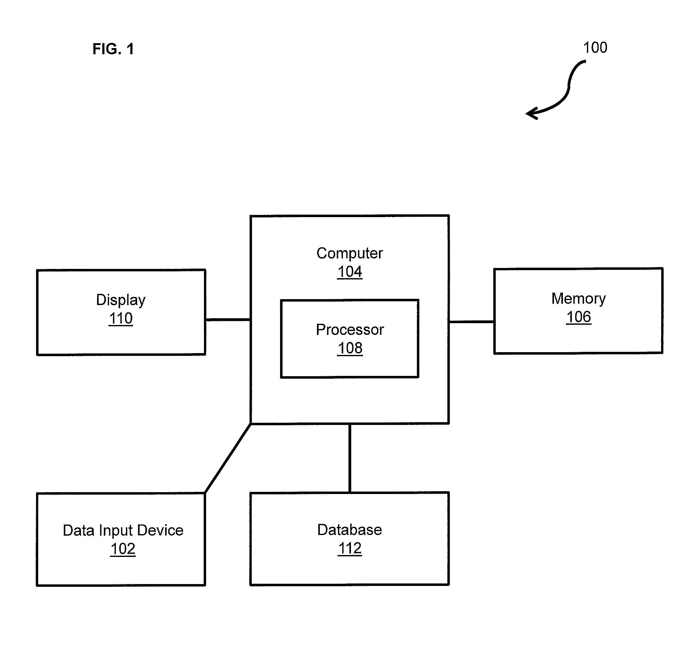
[0032]A block diagram of the anatomical recognition system 100 is shown in FIG. 1. One or more images are generated using imaging equipment (not shown) and inputted via a data input device 102 into a computer 104 that includes a memory 106. The data input device 102 may be any computer input device, including a keyboard, mouse, trackball, and scanner, or anything that can transfer the images from the data input device 102 to the computer 104. Images can be transferred directly from the imaging equipment, or alternatively stored in memory 106 of a computer 104 and transferred from the memory 106 to the computer 104. The computer 104 may be any general purpose personal computer (“PC”), server, or computing system including web-based computer systems and applications, such a...


PUM


Abstract

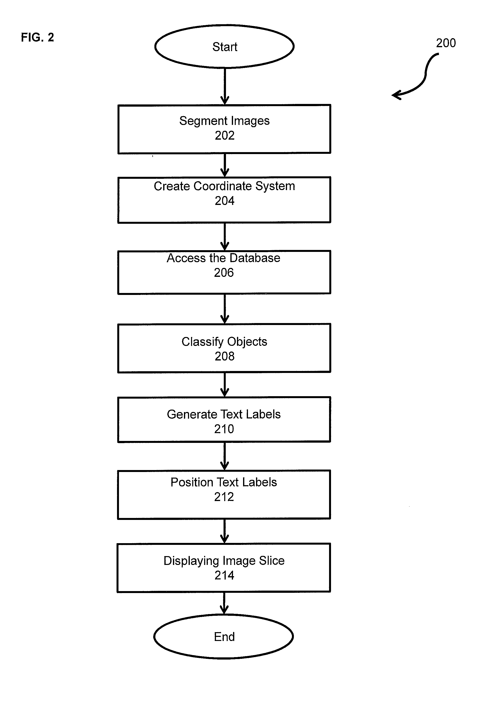
An imaging system and methods for processing a two-dimensional image from three-dimensional image information is disclosed. Images are segmented into foreground regions and background regions. An object-centered coordinate system is created and a hierarchical anatomical model is accessed to classify object in order to identify an anatomical object. The anatomical text labels are generated and positioned on the image slices and at least one image slice is displayed.

Description

[0001]This application claims the benefit of U.S. Provisional Application Ser. No. 61 / 355,710, filed Jun. 17, 2010, the disclosure of which is hereby incorporated by reference in its entirety.FIELD OF THE INVENTION[0002]The present invention relates generally to imaging, and more specifically to medical imaging and the automatic labeling of anatomical structures to identify radiographic anatomy in medical scans and further to assist in teaching radiographic anatomy of a subject. Anatomical structures are identified in a two-dimensional image, wherein the two-dimensional image is generated from three-dimensional image information. Specifically, the two-dimensional image is an image slice of a three-dimensional object.BACKGROUND[0003]Medical imaging has influenced many aspects of modern medicine. The availability of volumetric images from imaging modalities such as X-ray computed tomography (“CT”), magnetic resonance imaging (“MRI”), three-dimensional (“3D”) ultrasound, and positron e...

Claims


Application Information

Patent Timeline
IPC IPC(8): G06K9/00
CPCG06T11/00
Inventor BENN, DOUGLAS K.
Owner CREIGHTON UNIVERSITY
Learn More